I’m having an issue where my AML-S905X-CC will often crash if I plug in my hard drive, a 2TB WD My Passport external HDD, and if I try to boot with it connected, it gets stuck in a loop every time, which I can only solve by disconnecting the hard drive.
At first I figured it was an issue of power draw, so I routed it through a powered USB hub, but the issue persists. I’m having this issue on both of my (2) AML-S905X-CC boards. I don’t get this issue with flash drives or sd card (readers), just the external hard drive.
Any ideas of solutions?
OS used:
2022-09-22-raspbian-bullseye-arm64+aml-s905x-cc.img
ubuntu-22.04.1-preinstalled-desktop-arm64+aml-s905x-cc.img
both downloaded from the libre distro
Most likely the USB drive is not responding in time due to hard drive spinup time. You can disable the USB detection on startup or add a sleep delay before the USB detection.
How, exactly would one go about doing this? On my desktop this would be a piece of cake, but on the AML-S905X-CC I don’t even know where to start, or what to search for. Variations of the model name and “disable usb boot” only gives me results about booting from usb, with nothing helpful for disabling it…
encountered the same issue here. when i plug in my hard drive and the potato finally boots up, my hard drive shows up as 0B when i check for it in lsblk. how do i resolve this issue? i am trying to build a NAS here
i have just checked, my hard drive requires 5v 900mA to operate, but i understand that the le potato is only supplying 5v 500mA right, is there any way to resolve this?
Sounds like you need to power your hard drive from a separate source.
Some external drives provide a way to connect an external power source. If yours does not, you probably need to add a powered usb hub between the LePotato and your drive.
As for the power issue, I have a drive that consumes about 400mA, which should be well within the capacity of the USB port. Turns out that the Le Potato is supplying enough current, but not enough voltage. Only about 4.6V, which is below the drive’s supply specs. I ended up splicing a USB extension cable. Based on my experience so far, I would recommend always powering the drive directly instead of through the USB.
I got here because I have a similar problem with USB drives. Mine is a Samsung EVO 870 SATA 1TB SSD, and there are all matter of unsolvable issues with the drive connected, and it doesn’t matter if I’m running Armbian or Ubuntu, to the point I’ve considered giving up on Le Potato altogether for this project. I’ll try flashing the bootloader as suggested, and report on whether or not that helps.
Le Potato can supply 1A on each USB stack. The voltage at the USB ports depends on how good your power supply is. We have custom load devices drawing 1A from a USB port in our 24/7 labs powered through MicroUSB on the board with input voltage of 5.15 and output voltage of 4.9V @ 1A. So it’s probably your power supply.
My supply is a 5A laboratory power supply putting out a stable 5.00V (my less-than-lab-grade multimeter reads 4.95). I even scoped it. It’s clean. I doubt that is the problem.
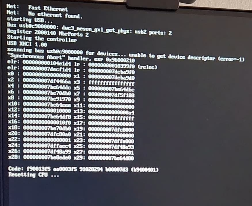
I flashed the bootloader (mmcblk0, as mmcblk1 does not exist). aml-s905x-cc and it yielded the same behavior as commonly observed with Armbian: apparently booting normally, then the heartbeat stops and it’s dead in the water. Another behavior observed with both Armbian and Ubuntu is that the drive activity light would flash for about a day before finally stopping, at which time the system may or may not be functional. I thought it was running fsck over and over, though I couldn’t imagine how a virgin ext4 file system without a journal could take much longer than some milliseconds, but examining the drive on my Mint system shows that it shouldn’t be running fsck at all. I don’t know what it was doing. I didn’t try again with Ubuntu. Flashing the bootloader with aml-s905x-cc-v2 wouldn’t boot at all, with or without the drive.
Now, even going back to an Armbian image that has worked reliably for weeks, assuming no mass storage was connected, it won’t boot at all. The heartbeat blinks twice and stops. Ubuntu will boot sometimes if I don’t try to enable SSH, and a headless system is useless without that. No clue why because none of them are leaving any boot logs. I was so pleased at first because the board came up and worked like a champ on the first try (I hadn’t added mass storage yet) and now it’s not working at all. I more and more suspect bad hardware as there has been a pattern of degradation. My experience with Le Potato has not been good. I’ve been doing electronics since before TTL logic and software since the IBM 370, and in that length of time you get a good feel for when to quit. In the meantime, I have some printed circuit boards to stuff and ARM and SAM firmware to debug.
5V at the lab supply does not mean 5V at the MicroUSB port. When current increases, wire resistance from the supply to the MicroUSB port will be very significant. Put one scope in the 5V header and set a 4.8V falling edge trigger. You will see that the voltage supplied to the board drops below that when load goes above a certain amperage.
It is called vdroop in electronics. Buy the correct power supply from our distributor.
Also certain USB devices will go over 900mA at peak. These devices cannot be powered by the board at all.
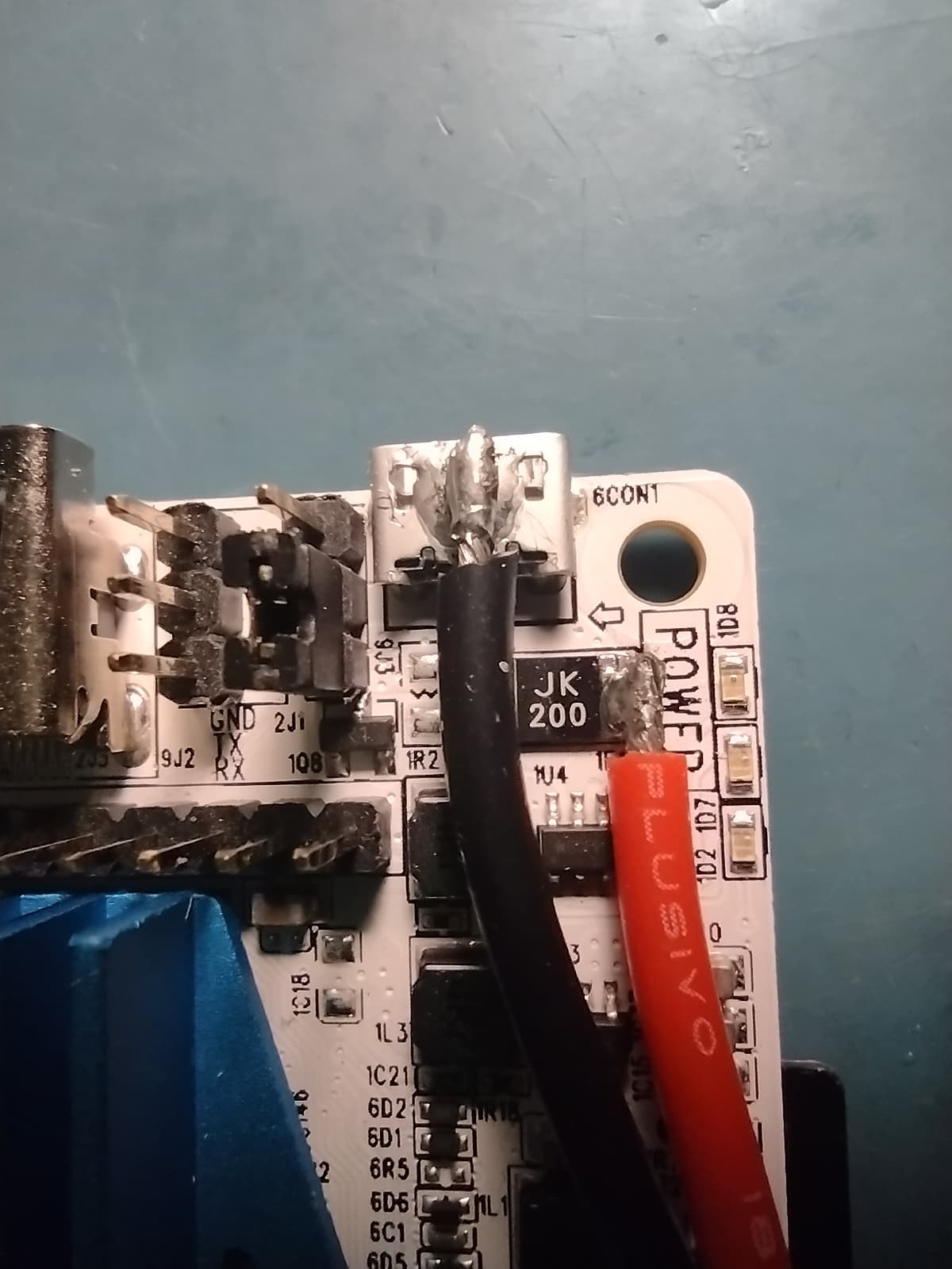
Yeah, I might have run into V=IR a time or two since the age of vacuum tubes. I actually rolled my eyes a bit because (1) There are only a few inches of vestigial USB cable between the board and my power leads that read 4.94V, and (2) the supply voltage on the board read 4.9-something when I started this. However, now it reads 4.64, which agrees with my USB power monitor after things got flaky. I didn’t expect it change. It seems to be that cursed MicroUSB connector. I can get the voltage to change by jiggling it. I’ve run into high contact resistance before, but I don’t think I’ve ever seen it develop like this. It does explain the progressive degradation I’ve observed. I’m going to solder power leads directly to the board. I already know which end of the PTC fuse is incoming, because I had already planned to do that anyway. Things should be back up in short order.
This seems like a great time to vent about that connector. It’s a blunder executed by the Raspberry Pi Foundation that others have faithfully mimicked. As configured, there are at least three significant failings:
USB-B is specified only to 1.5A. Anything requiring more should not use it.
USB cables, with the possible exception of USB-C, which I haven’t investigated, can have a wide range of power conductor gauges and cable lengths. Using one for a power supply for anything that draws more than a few milliamps and expecting 5V±5% is madness, as you have pointed out yourself. Even if you have a configuration that works, load regulation across the cable would be horrid. Phone charging circuitry is entirely different and can accommodate wider variations.
Such a connector without another route to supplying power is beyond just awkward. Suppose you put the board in a case with an internal supply and need to expose the HDMI port. How do you get power to it? Run a USB cable outside the box and plug it back in? With all the manufacturers these days, it’s strange that no one has figured that out. The same problem exists in applications that use mass storage and don’t have a SATA port. I’m going to have to solder to the board for that too. I wonder if people who design these boards ever try to use them in real-life projects.
They should use a barrel jack for power. It’ll fit. And at least a couple of pads with through-holes for attaching power leads internally. Several times I’ve thought of designing my own Linux-capable SBC, but I won’t because I would never recoup my development time unless I market it, and what I’d end up with would be very close to an Odroid-M1, which is nearly perfect. It uses a barrel jack. I probably couldn’t make it for less than the cost of the M1 and I really don’t want to mess with trying to match all those DRAM lines.
Thanks for the attention on the matter, though, and please excuse my rant.
We have been around since before the Pi 3 power fiasco where Pi 3 B and B+ will lose 0.75V at the input circuit (after the connector!) at high current. Our boards do not have this problem.
However, this cause Pi kit manufacturers to start pushing 5.75V to 6V power supplies marked as 5V which caused all kinds of issues. Search for “Le Potato no sound” as an example. We do not see Pi hardware in a favorable light due to these and other continued hardware design mistakes.
The connector is actually fine. We push around 2.5A with a 0.25V vdroop which is not an issue since the input voltage can be up biased to 5.25V. The issue is the quality of the cable and connector on that cable. Most cables are not designed for such high current. They use thin aluminum wires and high resistance soldering joints since the expected use case is USB 2.0 with 0.5A.
Our distributors have good power supplies that are designed with thicker copper cabling, good solder joints, and gold plated contacts to prevent conductor surface oxidation. We always use these in our labs and they work fine for the most intense loads.
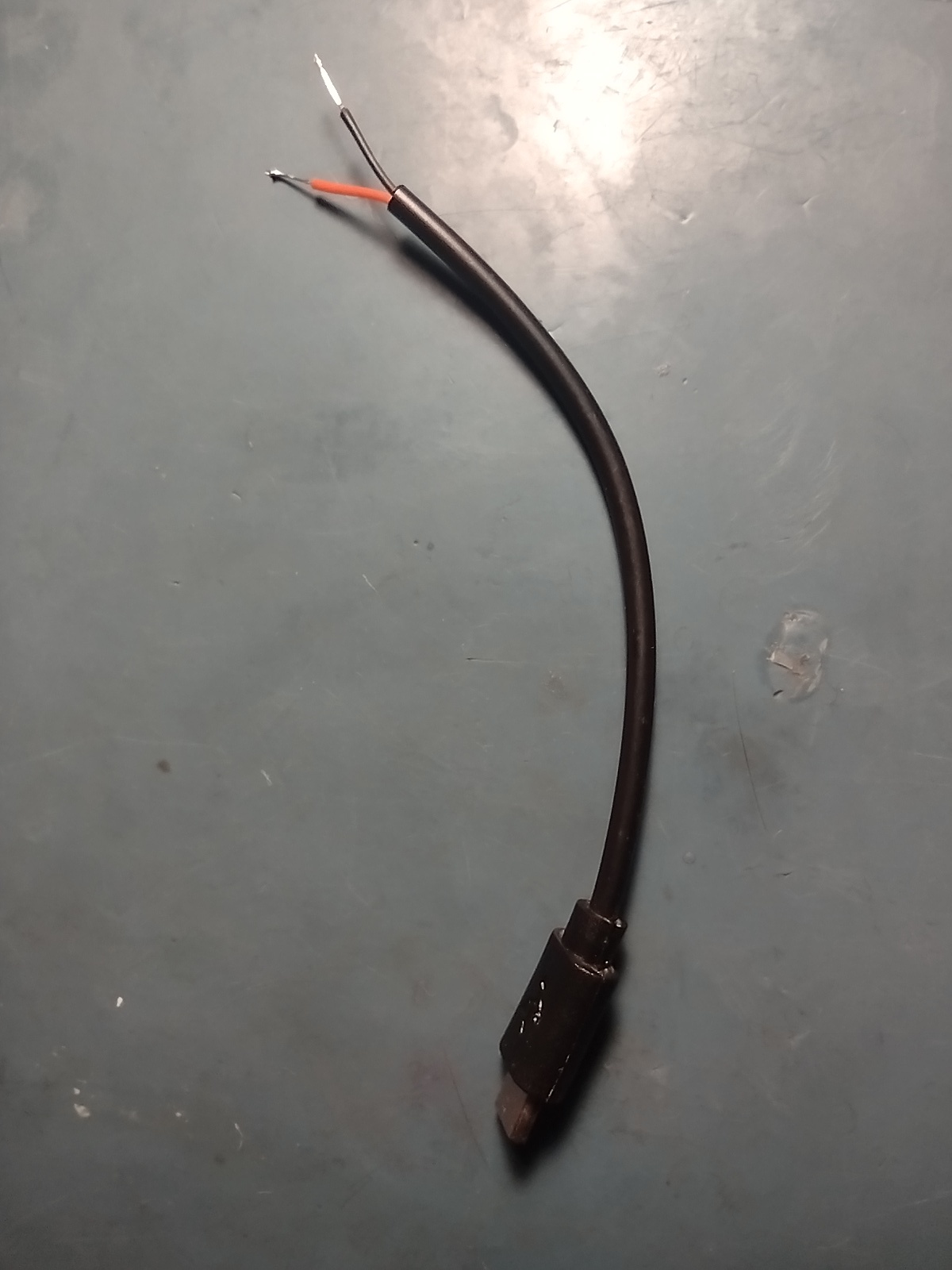
No, pushing 2.5A through a system spec’d for 1.5A is not fine, even if it happens to work. Sorting through cables for one with 22 gauge power conductors and searching Amazon for a 5.25V charger block is a burden users shouldn’t have to be shouldered with. Le Potato seems to be a fine board, especially for the price, but I’ll never agree on that USB connector. I’m sure my problem was with my USB pigtail, not the board, because it’s seen some use. It’s getting pitched. Pictures of my connector bypass, which works fine, and my USB pigtail, which doesn’t anymore, are attached.
We don’t recommend MicroUSB but 1.5A is not the system limitation. Conductors operate on basic physics of ohms per ft resistance varying based on wire thickness and contact area.
The longer the cable, the more ohms per ft of resistance. The smaller the contact area, the more resistance. It’s a very simple matter of Ohm’s law rather than some USB standards system design. If you have a long enough cable or thin enough wire, the connector does not matter and the system will fail.
Our distributors provide the right power supplies to deliver 5V 2.5A with minimum resistance that is sufficient to power 1A USB loads. Every part of that system is fine. If you use a thin wire gauge, that is why that specific system fails since it creates too much resistance, not because the connector cannot handle the current. The 5V and ground pin contact area on MicroUSB is more than sufficient to carry 3A.