Hello,
It is my first post here and I am a novice when it comes to SBC’s and Linux, so please excuse any mistakes made.
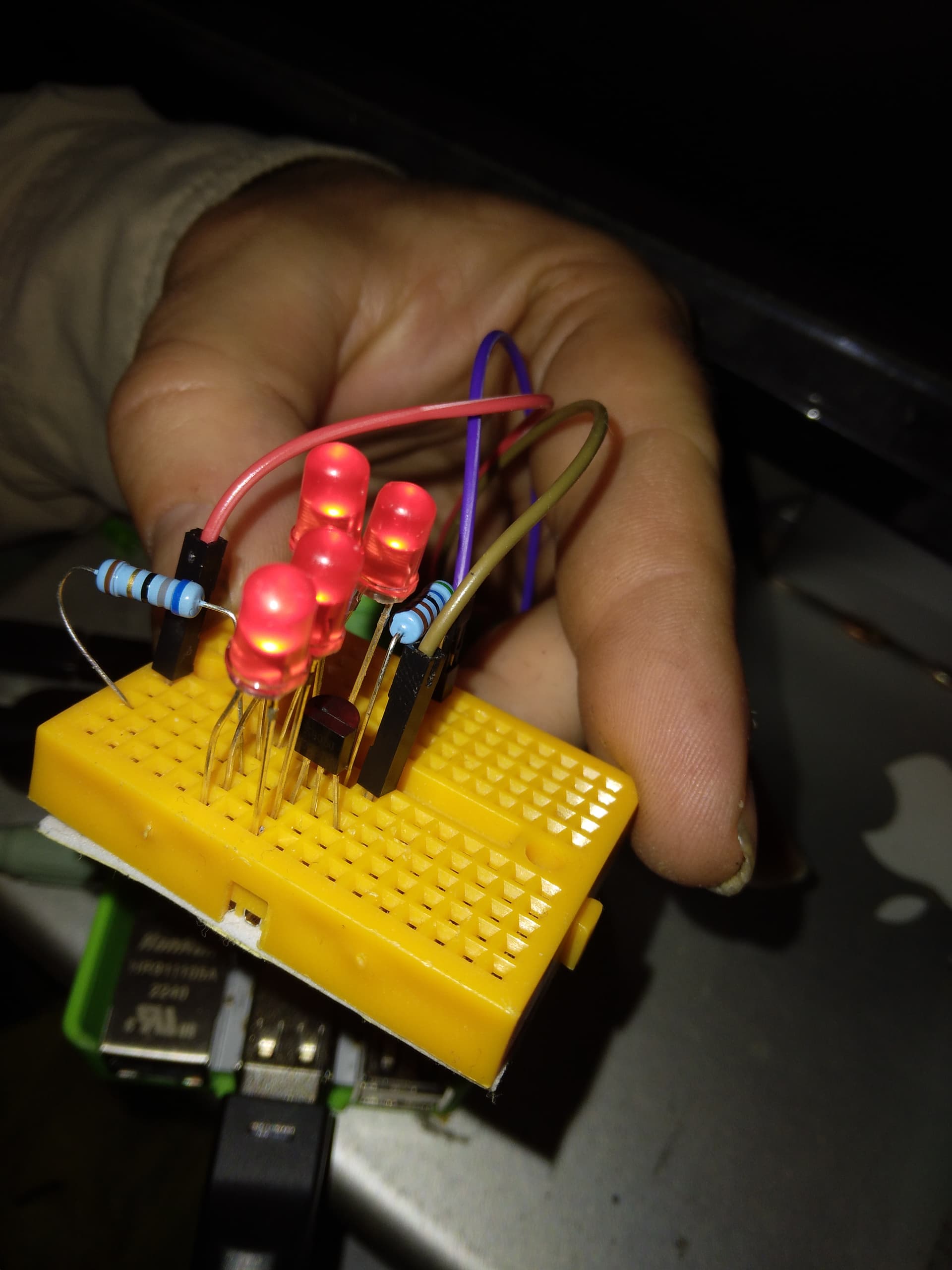
I have made a small breadboard circuit which consists of a 20mA LED with a resistor. That is then connected to a 2n222 transistor, with a resistor attached to the base for a voltage of 3.3v.
I have connected the base to a GPIO pin on the Le Potato (pin 36), but when connected, it makes the led only turn slightly on. (around 10-20% to my eyes) I was expecting it to surely power the LED especially with the LED’s power being handled by a external power supply. When I used lgpio to change the state of the GPIO pin, no change happened between states 0 and 1. I have tried rebuilding the circuit, replacing parts, changing GPIO pins but to no avail.
If anyone has had a similar issue and know of a fix to this, please let me know.
Thanks!
Hello, thank you for your quick response.
After testing the circuit with just the LED and resistor, the circuit seems to work fine.
The transistor is common and I had followed a guide on YouTube for the transistor circuit. The resistor is at 330 ohms. As he had released all calculations, and partially due that I had purchased a third party set of multiple types of NPN and PNP transistors, I don’t have the exact data sheet, although any you find on the internet should be fine. I have tested the transistor circuit with push buttons and it seems to work fine. The command I ran to change the value of the GPIO pin is: sudo lgpio set 36=1 and sudo lgpio set 36=0.
The Vf of the LED is 2-2.2v at 20mA. I am (rather was) running 4 LED’s in parallel using an external power supply and a transistor to help with the max current that can be released by the potato. After my calculations, it should be around 0.1mA of current, which surely should be enough for it to handle with the external power supply taking up most the work load?
I am again quite new to these sort of things so if you could give me an explanation to why this does not work that would be appreciated.
GPIOs can supply at least 2mA without any issues. 0.1mA is well within the support capability. Some SoCs have controllable drive strength for the GPIOs.
Hello,
I have seen this before and I am using this to control the GPIO pins but this does not mention anything about commands for drive strength as mentioned by the comment by Libre Computer.
Drive strength is not exposed in userspace. You cannot use it unless as part of a device tree overlay. Even then, it’s not supported on all boards. Worry about your application as this is beyond the scope of what you need.
So, all I had on hand for NPN transistors were s8050’s but looking at the datasheets it should be close enough. You didn’t give a lot of details, so I just sat down and worked out the math for my set-up.
Resistor 1 is a 68 ohm current limiting resistor for all 4 leds. According to my math you could use as low as a 22 ohm resistor for brighter LEDs, but this is what I had kicking around on my desk.
Resistor 2 is a 5.6K ohm current limiting resistor for a Base Current of about 0.5mA, plenty of overhead.
Connected:
Pin 4 (+5V) to Resistor 1 (68 ohm)
Resistor 1 to Positive leads of all 4 LEDs
Negative leads of all 4 LEDs to Collector of s8050
Emitter of s8050 to Pin 6 (Ground)
Base of s8050 to Resistor 2 (5.6K ohm)
Resistor 2 to Pin 36
Setting pin 36 to 1 turns them on; 0 turns them off.
Hello,
Could you let me know the formula you used to calculate the resistor values for the base of the transistor? I am not getting nearly close to your resistor values in my calculations.
Look at the data sheet and figure out how much current you want for your trigger signal. Leave some headroom. That is your Base Current (IB). For both of our transistors 0.6mA is more than enough to supply the needed 80mA, but not in excess of the 5mA limit. (Note in the formula we use A not mA.)
R = 3.3V / 0.0006A
R = 5500 Ω
I don’t have a 5.5k resistor, so 5.6k it is.
Divide the Voltage of the signal (3.3V in our case) by the Base Current, and Bob’s your uncle. Remember that using these as a switch means that we have plenty of wiggle room picking a resistor value. You could supply a whole range of different base currents that would make this circuit work. Just make sure not to exceed 5mA or go below the saturation point shown in the datasheet.
Admittedly, I chose values that would facilitate me not getting off my butt to get more components out.
Small update:
It appears that in addition to the resistor being calculated incorrectly, the circuit only works as expected when powered by the Le Potato and not with external power. This may have contributed to the problem, as the circuit still had the same issue even after using the recalculated resistor. I have checked the voltage of the external power, which is as expected, 5 volts, and the manufacturer has claimed up to 600mA of current, so I am unsure what could have caused the issue.
All that I have to say is that I am glad I finally have the circuit working.
Thanks again
Edit:
Do you know the max amperage the 5v pin can output on the Le Potato?