Could someone please tell me how to connect a power button to the le potato when using a LoverPi active cooling case with a fan? I’m new to this and I have connected the fan using the instructional video but I am unable to find information to add a power button for the Le potato, there are plenty of instruction for the Raspberry Pi. This is the button I’m trying to connect XMSJSIY Chassis Switch Host Metal… Amazon.com
If someone could please explain this clearly in grade school terms, I would greatly appreciate it.
Thank you
I’m very new to all of this myself, but I just figured out something that might help!
If you check out gpio pin header maps for the Le Potato and read the print at the bottom you may notice that linux# pin 10 can be pulled down to reset the system. I ran a test with a ground wire and when connected to that gpio pin (the eighth one down from the left side with the IR unit facing up and the usb facing down) and it indeed turned off the system! So with this knowledge I’ve wired up a simple off switch on a breadboard with the ground on one side and the pin on the other, so when you press it, the system resets. I’m not sure if this is the best method, but keeping the ground connected to that pin will turn off the system and could easily make an on off switch. Is it the right way to do it? I don’t know, but hopefully this is helpful or interesting
Thank you for replying. I have added a picture to my post of the leads attached to the button (for visual reference). The red and black lead are separate and the green and blue are attached to each other. Where would I attach the other cables?
So, I’m guessing here (and I think I might have messed up pin 10 on my le potato just tinkering further), but the blue two female plug is probably what is triggered by the switch, when it is pressed it probably connects the two, so, in that assumption, if you have some female to male wires, you could plug a female side to a ground (see the header map again), and to one side of the the POWER SW and plug another female to male wire on the pin 10, the low pull reset pin (again, check the header map) to the other side of POWER SW. When you press the button I’d imagine it would hold the reset. But I wouldn’t do this without a bit more testing or you might end up where I am, with a pin 10 that I can’t seem to figure if I’ve fried or not.
Something easier to figure out might be lighting up the ring on this button, which might be as simple as hooking the POWER LED+ to a powered pin (like row 1 pin 1) and POWER LED- to a ground GND pin.
If you have a breadboard and a power source you can wire to it, I’d try it on the breadboard first since there is less risk. But since I don’t have a power button like this to try out, I hand this experiment back to you. Hopefully this extra bit spurs you to try a few things, and if I figure out any more I’ll post again
Not sure if you managed to resolve this yet, but I’ve been looking into this myself. I’m also very new at this.
I actually haven’t gotten my Le Potato yet, as I literally just bought it, but the way I plan on setting mine up is, I purchased one of these from LoveRPI.com
That power adapter actually has a hard power button built right into it. Then I’ll just have the front button on the case act as a reset button.
I think you have the right idea. There doesn’t appear to be an easy route to a gpio on/off switch. I use a powerstrip so I can kill the whole setup with one switch.
If you run sudo shutdown -H now it will halt the machine so you have time to hit the switch on the power supply, otherwise it will reboot automatically when shutdown.
Working out how to give myself permission to run this without sudo is on my to-do list.
And then what will cause the unit to start again? Turning the power off and on again?
Does this mean that a momentary switch on the power input would act as a way to turn the unit on again after it has been shut down with the gpio-key press?
If you halt a machine, the only way to restart is to switch power off and back on again. Momentary power off can be done with the power supply show previously by softly pressing the power button to cut power.
I agree, this is probably the safer way to do it. I will go this route.
So when you’re programming the GPIO, you can use the same commands as the RPi, correct?
Thanks
Hi,
With the IR receiver programmed with ir-keytable, inputlirc and irexec ; two buttons (on my IR remote), one for “shutdown -H” and another for 'reboot". They works fine.
If you read the gpio-keys documentation, it says you can use either the gpios field or the interrupts field, not both. Because the platform does not have a gpio_to_irq function, it tries to bind to the IRQ that is actually the GPIO number which is wrong. The IRQ number and GPIO number are different from each other. The implementation is simple and straight forward:
@librecomputer Could you compile a .dtb of this .dts for us to add to our “device_trees” folder on the sd card? You should make a guide. If you want people to buy your products you have to make it easy for everyone of every skill level to understand and implement.
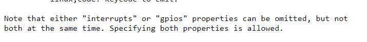
“If you read the gpio-keys documentation, it says you can use either the gpios field or the interrupts field, not both.”
Is this accurate? my interpretation of the documentation was that either gpios can be omitted (left out) but not both, and both can have a value (see attached image). Or have I misunderstood the document?
How do you do this? I see from documentation and examples that it is possible to bind to a key input (ie. keyboard, button, etc) but it is not clear how to bind to a command line such as “shutdown -H now”. Can you explain this in more detail please