I’m trying to get this bme688 to work: BME688 4-in-1 Air Quality Breakout (Gas, Temperature, Pressure, Humidity)
I believe that I have installed the prerequisite software but the example code is not working. How can I check to make sure the device has been connected properly?
From what I can tell, I need to enable i2c with raspi-config. Then I should be able to run i2cdetect to see what is connected but I’m not sure how to interpret what I’m seeing:
$ sudo i2cdetect -y 0
     0  1  2  3  4  5  6  7  8  9  a  b  c  d  e  f
00:                         -- -- -- -- -- -- -- --
10: -- -- -- -- -- -- -- -- -- -- -- -- -- -- -- --
20: -- -- -- -- -- -- -- -- -- -- -- -- -- -- -- --
30: 30 -- -- -- -- -- -- -- -- -- -- -- -- -- -- --
40: -- -- -- -- -- -- -- -- -- -- -- -- -- -- -- --
50: -- -- -- -- -- -- -- -- -- -- -- -- -- -- -- --
60: -- -- -- -- -- -- -- -- -- -- -- -- -- -- -- --
70: -- -- -- -- -- -- -- --
$ sudo i2cdetect -y 1
Error: Could not open file `/dev/i2c-1' or `/dev/i2c/1': No such file or directory
I have the device soldered onto pins 1,3,5, and 9. I think I’m supposed to see a device at “0x77” but I’m not sure what that means.
Any help or advice given would be appreciated. Thanks!
Update:
I followed this guide here: How to Enable I2C on AML-S905X-CC Le Potato, but I missed the merge part on my first attempt.
I now see this when I run i2cdetect
$ i2cdetect -y 0
     0  1  2  3  4  5  6  7  8  9  a  b  c  d  e  f
00:                         -- -- -- -- -- -- -- --
10: -- -- -- -- -- -- -- -- -- -- -- -- -- -- -- --
20: -- -- -- -- -- -- -- -- -- -- -- -- -- -- -- --
30: -- -- -- -- -- -- -- -- -- -- -- -- -- -- -- --
40: -- -- -- -- -- -- -- -- -- -- -- -- -- -- -- --
50: -- -- -- -- -- -- -- -- -- -- -- -- -- -- -- --
60: -- -- -- -- -- -- -- -- -- -- -- -- -- -- -- --
70: -- -- -- -- -- -- -- --
$ i2cdetect -y 1
     0  1  2  3  4  5  6  7  8  9  a  b  c  d  e  f
00:                         08 09 0a 0b 0c 0d 0e 0f
10: 10 11 12 13 14 15 16 17 18 19 1a 1b 1c 1d 1e 1f
20: 20 21 22 23 24 25 26 27 28 29 2a 2b 2c 2d 2e 2f
30: 30 31 32 33 34 35 36 37 38 39 3a 3b 3c 3d 3e 3f
40: 40 41 42 43 44 45 46 47 48 49 4a 4b 4c 4d 4e 4f
50: 50 51 52 53 54 55 56 57 58 59 5a 5b 5c 5d 5e 5f
60: 60 61 62 63 64 65 66 67 68 69 6a 6b 6c 6d 6e 6f
70: 70 71 72 73 74 75 76 77
$ i2cdetect -y 2
     0  1  2  3  4  5  6  7  8  9  a  b  c  d  e  f
00:                         -- -- -- -- -- -- -- --
10: -- -- -- -- -- -- -- -- -- -- -- -- -- -- -- --
20: -- -- -- -- -- -- -- -- -- -- -- -- -- -- -- --
30: 30 -- -- -- -- -- -- -- -- -- -- -- -- -- -- --
40: -- -- -- -- -- -- -- -- -- -- -- -- -- -- -- --
50: -- -- -- -- -- -- -- -- -- -- -- -- -- -- -- --
60: -- -- -- -- -- -- -- -- -- -- -- -- -- -- -- --
70: -- -- -- -- -- -- -- --
Please provide a photo of your wiring setup. Reset, reboot, and then use ldto enable and probe the highest I2C bus.
I reinstalled the OS and redid the ldto. Here’s the result of the i2cdetect command
$ sudo i2cdetect -y 0
     0  1  2  3  4  5  6  7  8  9  a  b  c  d  e  f
00:                         -- -- -- -- -- -- -- --
10: -- -- -- -- -- -- -- -- -- -- -- -- -- -- -- --
20: -- -- -- -- -- -- -- -- -- -- -- -- -- -- -- --
30: -- -- -- -- -- -- -- -- -- -- -- -- -- -- -- --
40: -- -- -- -- -- -- -- -- -- -- -- -- -- -- -- --
50: -- -- -- -- -- -- -- -- -- -- -- -- -- -- -- --
60: -- -- -- -- -- -- -- -- -- -- -- -- -- -- -- --
70: -- -- -- -- -- -- -- --
$ sudo i2cdetect -y 1
     0  1  2  3  4  5  6  7  8  9  a  b  c  d  e  f
00:                         08 09 0a 0b 0c 0d 0e 0f
10: 10 11 12 13 14 15 16 17 18 19 1a 1b 1c 1d 1e 1f
20: 20 21 22 23 24 25 26 27 28 29 2a 2b 2c 2d 2e 2f
30: 30 31 32 33 34 35 36 37 38 39 3a 3b 3c 3d 3e 3f
40: 40 41 42 43 44 45 46 47 48 49 4a 4b 4c 4d 4e 4f
50: 50 51 52 53 54 55 56 57 58 59 5a 5b 5c 5d 5e 5f
60: 60 61 62 63 64 65 66 67 68 69 6a 6b 6c 6d 6e 6f
70: 70 71 72 73 74 75 76 77
$ sudo i2cdetect -y 2
     0  1  2  3  4  5  6  7  8  9  a  b  c  d  e  f
00:                         -- -- -- -- -- -- -- --
10: -- -- -- -- -- -- -- -- -- -- -- -- -- -- -- --
20: -- -- -- -- -- -- -- -- -- -- -- -- -- -- -- --
30: 30 -- -- -- -- -- -- -- -- -- -- -- -- -- -- --
40: -- -- -- -- -- -- -- -- -- -- -- -- -- -- -- --
50: -- -- -- -- -- -- -- -- -- -- -- -- -- -- -- --
60: -- -- -- -- -- -- -- -- -- -- -- -- -- -- -- --
70: -- -- -- -- -- -- -- --
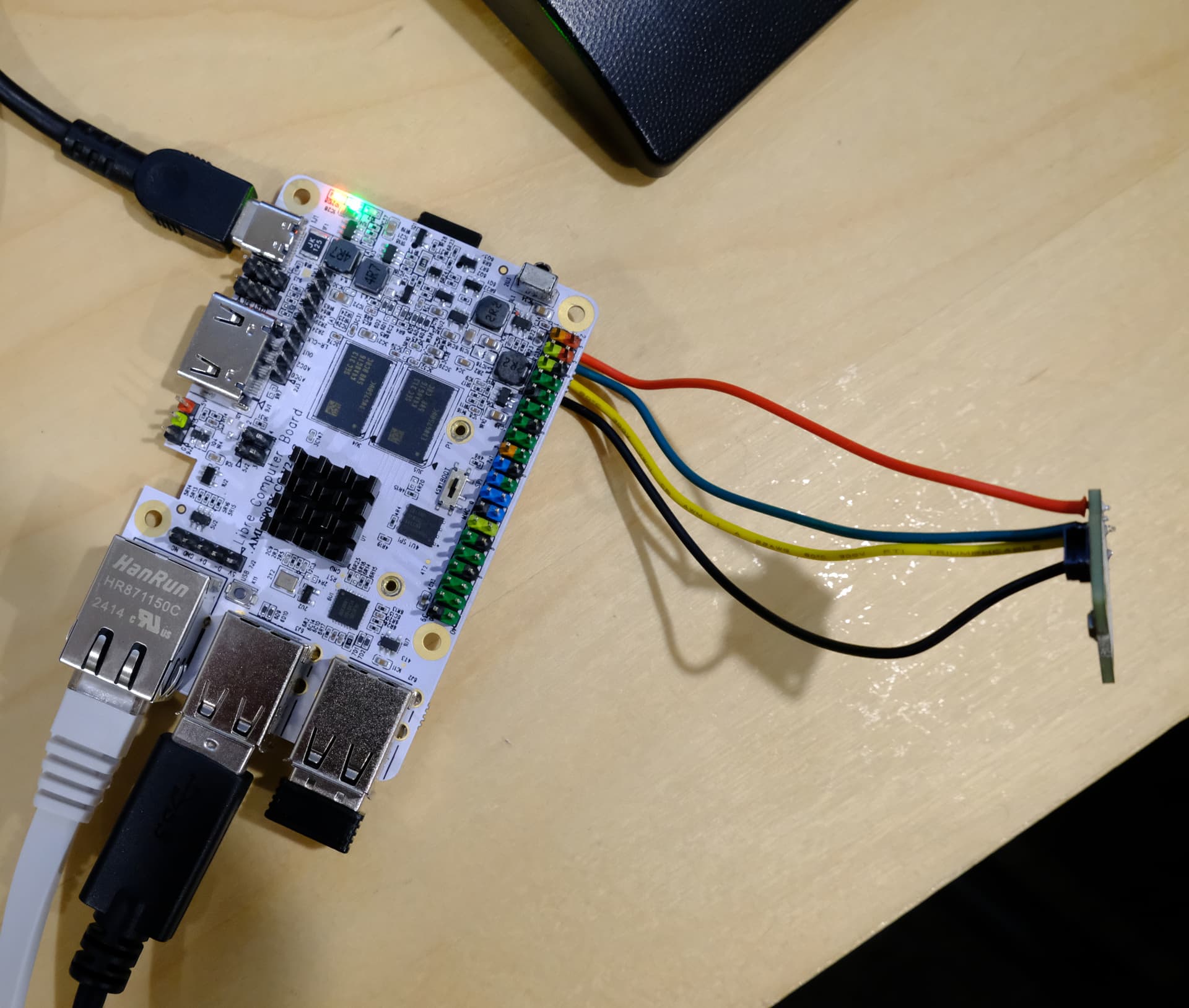
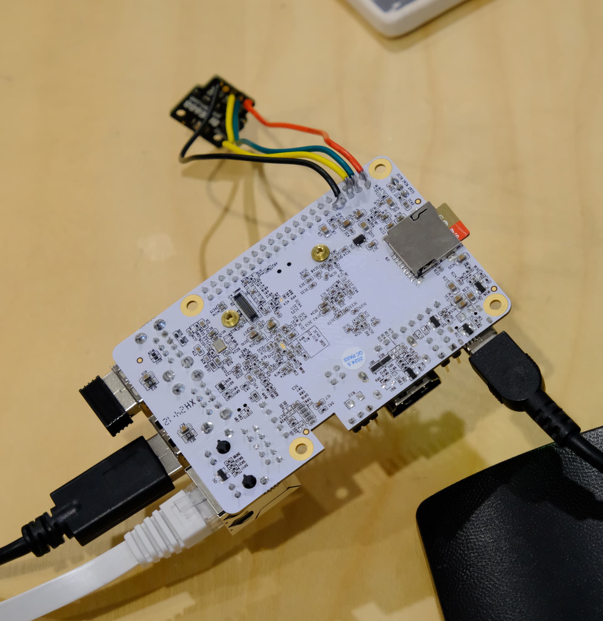
Here’s some photos of the physical wiring setup.
The wires are not touching each other or the other pins. I used a multimeter to verity continuity from the top of the header pins on the board to the through holes on the air sensor board.
I did one last check before posting to verify and I noticed that there seems to be continuity between ground on the air sensor and pins 1 and 2 but only when powered on. I’m guessing that’s the issue.
The board itself seems okay. There’s no continuity between ground and the rest of those pins, just the air sensor.
You should use headers and not solder the board on the back side. There should be no short circuits.
Why is there 3 I2C buses? You need to provide all the commands you entered. The only overlay that should be enabled is i2c-ao.
I’m not sure why there are 3 I2C buses, just followed the guide mentioned previously. I guess it doesn’t matter because it’s working now. I removed the solder connections from the back and used the header pins with a breadboard. The device is detected now:
 sudo i2cdetect -y 1
     0  1  2  3  4  5  6  7  8  9  a  b  c  d  e  f
00:                         -- -- -- -- -- -- -- --
10: -- -- -- -- -- -- -- -- -- -- -- -- -- -- -- --
20: -- -- -- -- -- -- -- -- -- -- -- -- -- -- -- --
30: -- -- -- -- -- -- -- -- -- -- -- -- -- -- -- --
40: -- -- -- -- -- -- -- -- -- -- -- -- -- -- -- --
50: -- -- -- -- -- -- -- -- -- -- -- -- -- -- -- --
60: -- -- -- -- -- -- -- -- -- -- -- -- -- -- -- --
70: -- -- -- -- -- -- 76 --
I’m even able to run my python examples and get sensor readings!
Thanks for your help and sorry you had to see your board treated so brutally. I was planning on using the PoE hat but the connections blocked the i2c header pins. So I guess when I finalize this project I’ll need to use header pin extenders or something.
Out of pure curiosity, why wouldn’t soldering on the bottom work? I thought it would because the continuity tests.
You probably have a short somewhere.