I configured my Arduino following a tutorial on YouTube to receive on I2C address 0x8 to turn the led on and off, just as a way to test it.
Now running
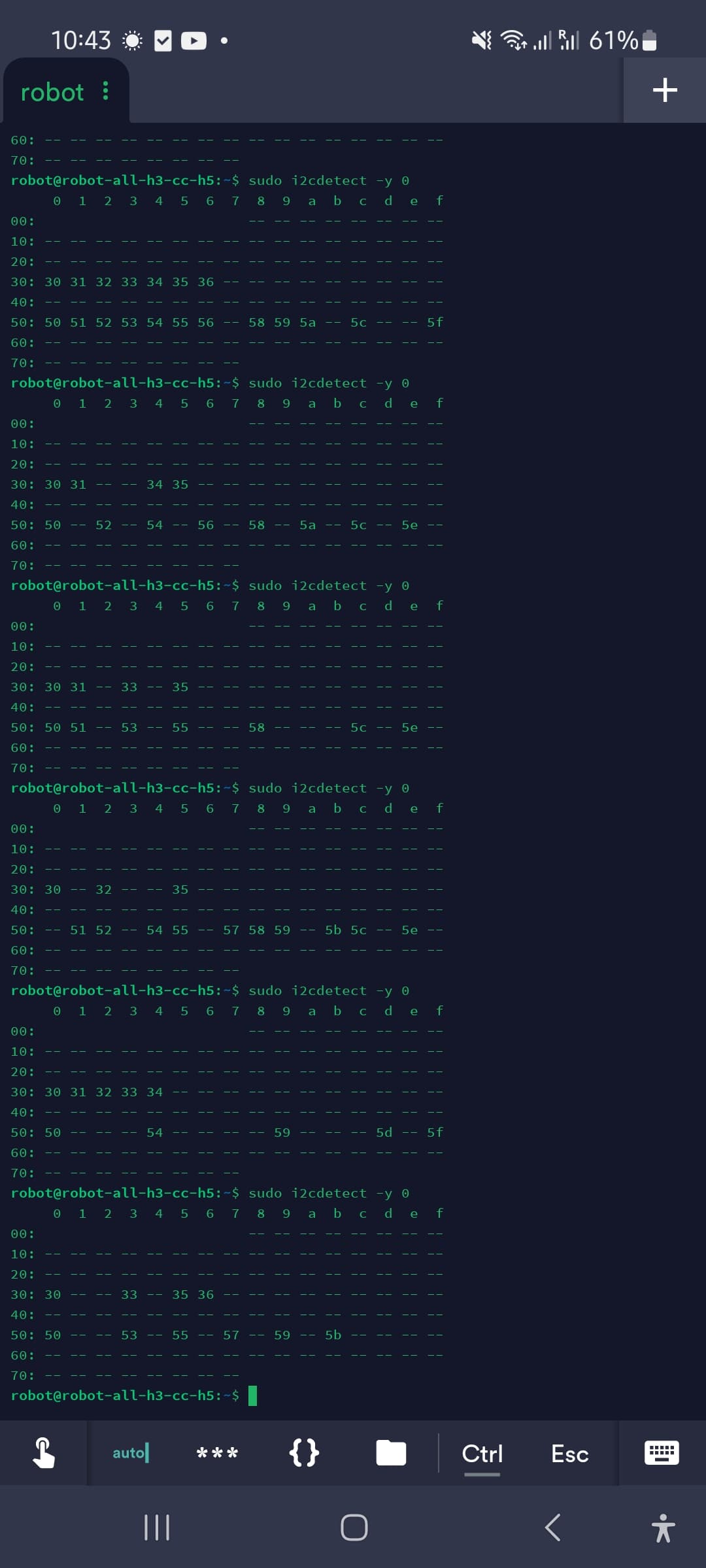
sudo i2cdetect -y 0
gives me random I2C adresses but no address 0x8. Also running the command multiple times gives me a different output every time.
I also tried disconnecting all the cables from my Tritium and I still get random I2C adresses. You can see the output on my screenshot. (Screenshot is without any I2C devices connected. So it should give an empty list, but the list changes every time)
Have you applied a Device Tree Overlay? Usually the I2C bus created when an overlay is enabled comes after the bus used by the board. I believe what you’re seeing is a built in EEPROM or some-such on an I2C bus that is used for the boards own purposes.
Here’s the how-to:
This is what it looks like on the AML-S905X-CC (I don’t have one of the Allwinner boards to test with. My I2C device lives at 0x36.):
I don’t really understand, do you think I need to install the device tree overlay and it will somehow allow me to use the I2C pins? I’m really new to all this GPIO, SBC and Linux stuff, I’m still trying to get my bearings
Yes, again, I’m using a different board, so my pins/overlays will be different, but you need to enable the I2C bus you want to use in the device tree, or the kernel doesn’t know it’s there.
The wiring tool should come pre-installed if you’re using one of Libre’s images, and the command ldto list will tell you what overlays are available for your board.
It’s a bit different than what I get on my board, but it looks like sudo ldto enable i2c1-twi0 should get you up and running on pins 3 and 5, using /dev/i2c-1. If I’m wrong hopefully someone with and Allwinner board in hand can correct me.
You will need to reapply the overlay after each boot. You can add it permanently by replacing “enable” wit “merge”. Be aware on my board this flips the busses, so the internal use bus becomes i2c-1 and the one I attached my device to becomes i2c-0.
Hope that sheds some light. The Device Tree is a huge topic, so don’t worry if you don’t get it all at once!
EDITS: Corrected spelling, and it’s open on my browser so I may as well link to the pin-maps:
I tried with enable first, it worked! I got a completely empty list without anything attached and plugging in the logic converter I got something on 0x8!
The one I had to activate was i2c0-twi0 (according to the pinout thats on pin 3-5, i2c1-twi1 is on pin 20something)
I broke a cable off my logic converter while trying to get it into my enclosure, so testing the Arduino sketch will have to wait, but so far I feel like I’m a major step closer, being able to see the Arduino on address 0x8 means that at least this part of my sketch works!
Thanks a lot for your help, I found that first article you linked before but didn’t make the connection with I2C since it’s not mentioned anywhere.