Klipper ADXL345 Wiring / SPI / UART

ADXL345 Wiring to RPI

This would also need to work with SPI touch screens or possible other devices connected at the same time to serial.

Another request would be UART connection to power but also send/receive between a 3D printer controller and S905x.

https://www.printables.com/model/114229-skr-14-turbo-raspberry-pi-direct-serial-connection

@Da_Xue if you need any hardware for this to test, I can send to you.

@Da_Xue below is a sample of a software spi config used on a toolboard.

sample
#[adxl345] #experimental board working on
#cs_pin: head0:PB10
#spi_software_sclk_pin: head0:PA13
#spi_software_mosi_pin: head0:PA14
#spi_software_miso_pin: head0:PB11
#axes_map: -z,x,-y

proposed
#[adxl345] #experimental board working on
#cs_pin: LePotato:LePotato:hardware_pin-x
#spi_software_sclk_pin: LePotato:software_spi-x
#spi_software_mosi_pin: LePotato:software_spi-xx
#spi_software_miso_pin: LePotato:software_spi-xxx
#axes_map: -z,x,-y

Based on the wiring, you can use:

libretech-wiring-tool

sudo ./ldto enable spicc
sudo ./ldto enable spicc-spidev
ls /dev/spidev0.0

What about using this at the same time as the ADS7846 screen? You mentioned software SPI as a possibility but both utilize the same hardware pins. The screen has solder breakouts – just wondering how this would work if both were plugged in at the same time ?

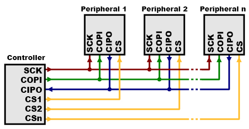
SPI multiplexing is done via chip-select. Devices would share the SPI pins and each SPI endpoint would be enabled by the chip-select.

There are spicc-cs1 and spicc-cs1-spidev. Depending on whether you are using the kernel driver or an userspace driver, you would create a new overlay to map your devices.

What is the best way to run additional CS wires into the S905X?
image

Yes, you would have pin 24 and 26 as the chip enables for two endpoints.