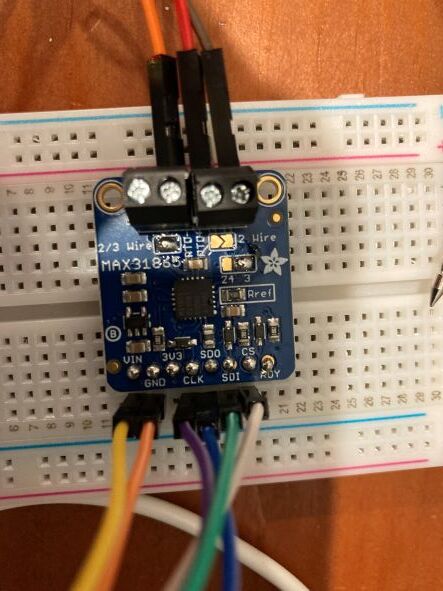
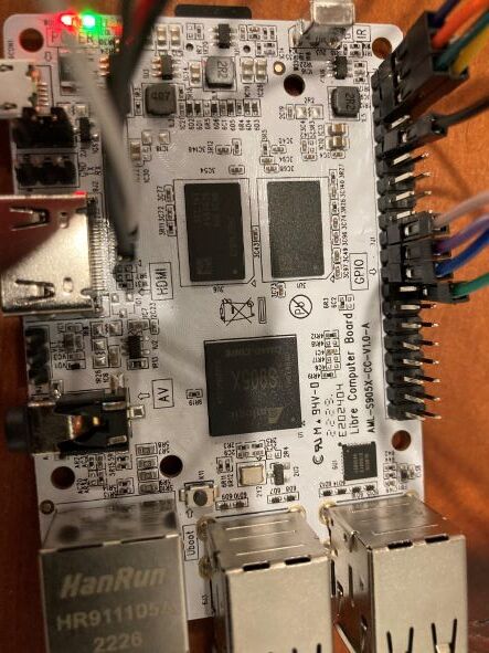
Hello, I’m a relative newbie and I’m looking for some advice. My MAX31865 RTD amp will not work. I am using a Le Potato w/ the Raspbian OS from the Distro server. Libretech wiring tools w/ spi and spicc and spicc-spidev enabled. I’m using a MAX31865 RTD amp w/ a PT1000 RTD. Correct ref resistor (4300 Ohms). Wiring is double-checked, solder joints double-checked. Replaced the MAX board once. When I query the amp I get 0 Ohms on the RTD. I’m using a 3-wire RTD and have jumpered the board appropriately (closed the 2/3 wire jumper, the 3/4 jumper, and opened the 2/4 junction with a cut). As I’ve double-checked the hardware, I am thinking this is a comms issue, maybe something associated with the Libre? Code and photos below. There is one last piece of the puzzle that I don’t understand, and maybe this will be the solution: when I try and use pin 24 as my chip select, I get an error (“Device or Resource Busy”). This board is simultaneously running a temperature sensor using I2C, but those are completely different pins and wiring.
I uninstalled and reinstalled blinka last week. I noticed that some Libre functionality had just been added to some of my libraries, I don’t recall which one.
display_bus = displayio.FourWire(
File “/usr/local/lib/python3.9/dist-packages/displayio/_fourwire.py”, line 64, in init
self._chip_select = digitalio.DigitalInOut(chip_select)
File “/usr/local/lib/python3.9/dist-packages/digitalio.py”, line 165, in init
self.direction = Direction.INPUT
File “/usr/local/lib/python3.9/dist-packages/digitalio.py”, line 195, in direction
self._pin.init(mode=Pin.IN)
File “/usr/local/lib/python3.9/dist-packages/adafruit_blinka/microcontroller/generic_linux/libgpiod_pin.py”, line 108, in init
self._line.request(
OSError: [Errno 16] Device or resource busy
This is the result when I try and use pin 24 as CS:
Traceback (most recent call last):
File “/home/pi/RTDampSPI.py”, line 9, in
cs = digitalio.DigitalInOut(board.P24) # Chip select of the MAX31865 board.
File “/usr/local/lib/python3.9/dist-packages/digitalio.py”, line 165, in init
self.direction = Direction.INPUT
File “/usr/local/lib/python3.9/dist-packages/digitalio.py”, line 195, in direction
self._pin.init(mode=Pin.IN)
File “/usr/local/lib/python3.9/dist-packages/adafruit_blinka/microcontroller/generic_linux/libgpiod_pin.py”, line 115, in init
self._line.request(config)
File “/usr/local/lib/python3.9/dist-packages/gpiod/libgpiodcxx/init.py”, line 572, in request
rv = libgpiod.gpiod_line_request(_m_line, conf, default_val)
File “/usr/local/lib/python3.9/dist-packages/gpiod/libgpiod/init.py”, line 499, in gpiod_line_request
return gpiod_line_request_bulk(bulk, config, [default_val])
File “/usr/local/lib/python3.9/dist-packages/gpiod/libgpiod/init.py”, line 542, in gpiod_line_request_bulk
return _line_request_values(bulk, config, default_vals)
File “/usr/local/lib/python3.9/dist-packages/gpiod/libgpiod/init.py”, line 403, in _line_request_values
status = ioctl(fd, GPIO_GET_LINEHANDLE_IOCTL, req)
OSError: [Errno 16] Device or resource busy
Unfortunately I don’t have one of these amplifiers but looking at the instructions and your photos everything looks good.
I was going to suggest just using 2 wire and putting a resistor across as a test but I see that’s not practical seeing all the soldered configuration for 3 wire.
Do you have another SPI device that you could test ?
I haven’t tried the loopback test below but if you’ve run out of options it might be worth a try ???
Great idea! I don’t have another SPI device to test, but I did the loopback test and I believe it worked (output below). In the example they give on the website, “spi mode:” is “0”, however here it is “4”. Any thoughts on why that might be the case?
pi@raspberrypi:~ $ ./spidev_test -D /dev/spidev0.0
spi mode: 4
bits per word: 8
max speed: 500000 Hz (500 KHz)
FF FF FF FF FF FF
40 00 00 00 00 95
FF FF FF FF FF FF
FF FF FF FF FF FF
FF FF FF FF FF FF
DE AD BE EF BA AD
F0 0D
If you are using spicc-cs1-spidev, /dev/spidev0.0 enables pin 24 CS and /dev/spidev0.1 enables pin 26 CS. Whatever library you are using is doing something funny (not correct).