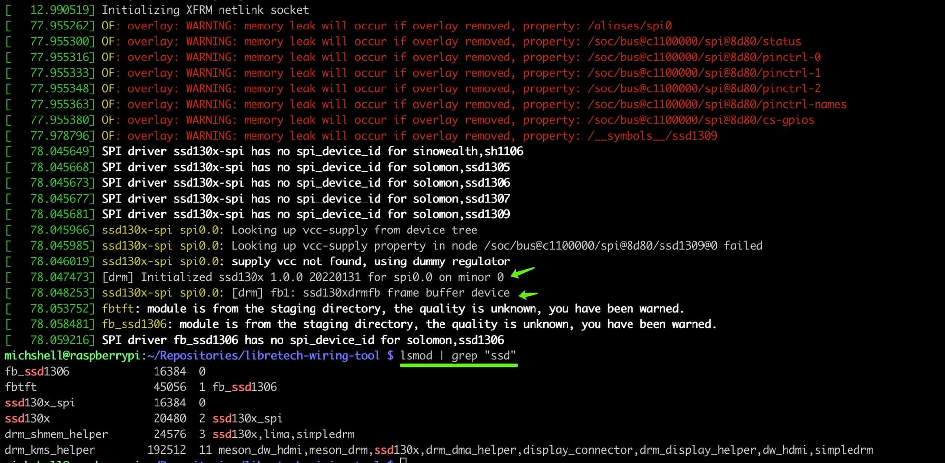
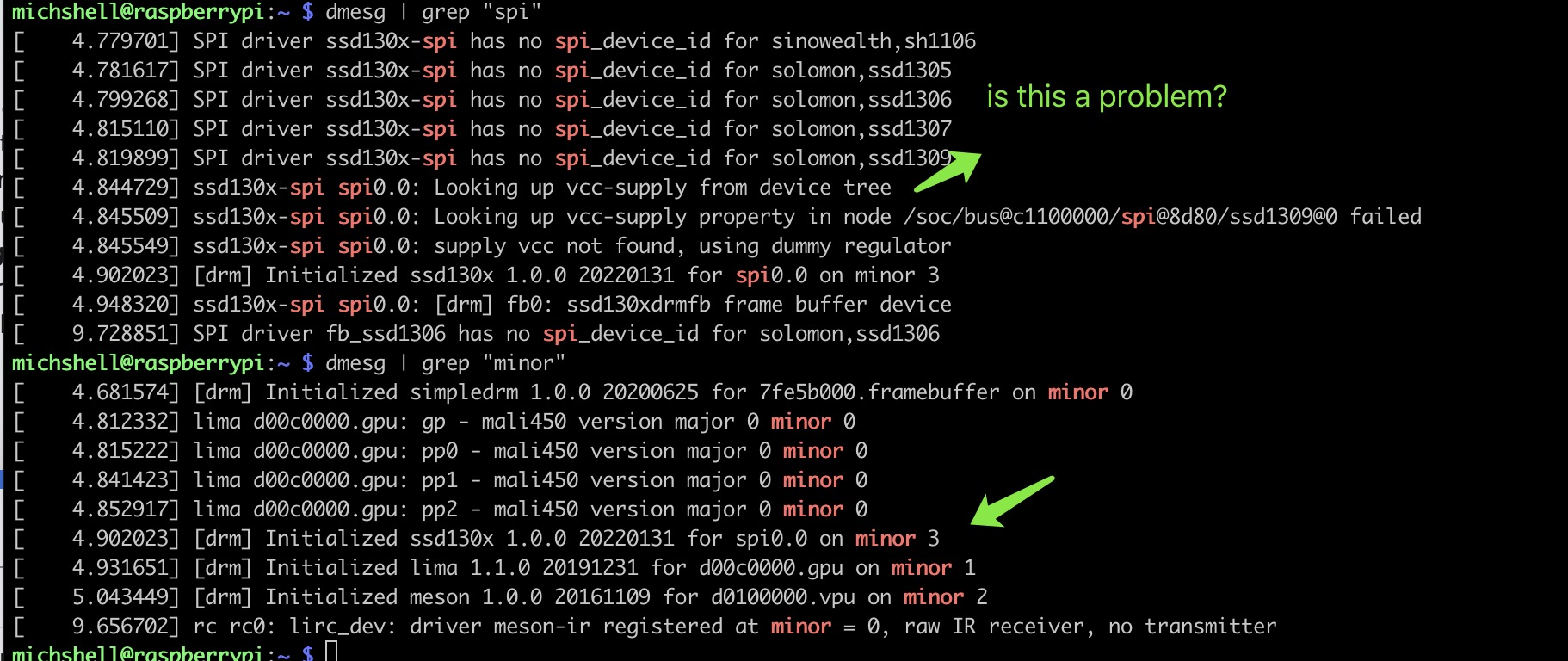
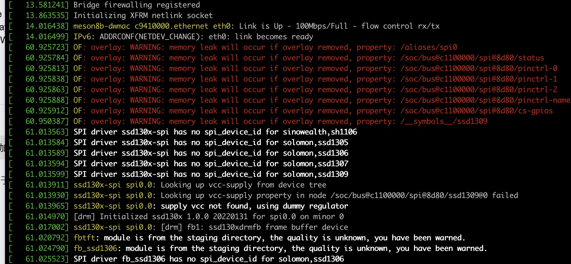
"OSError: [Errno 16] Device or resource busy" for SPI device

Hello,

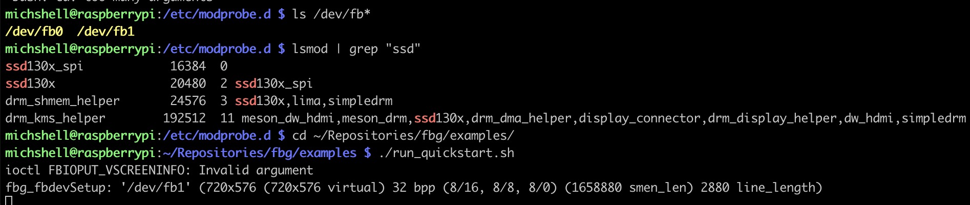
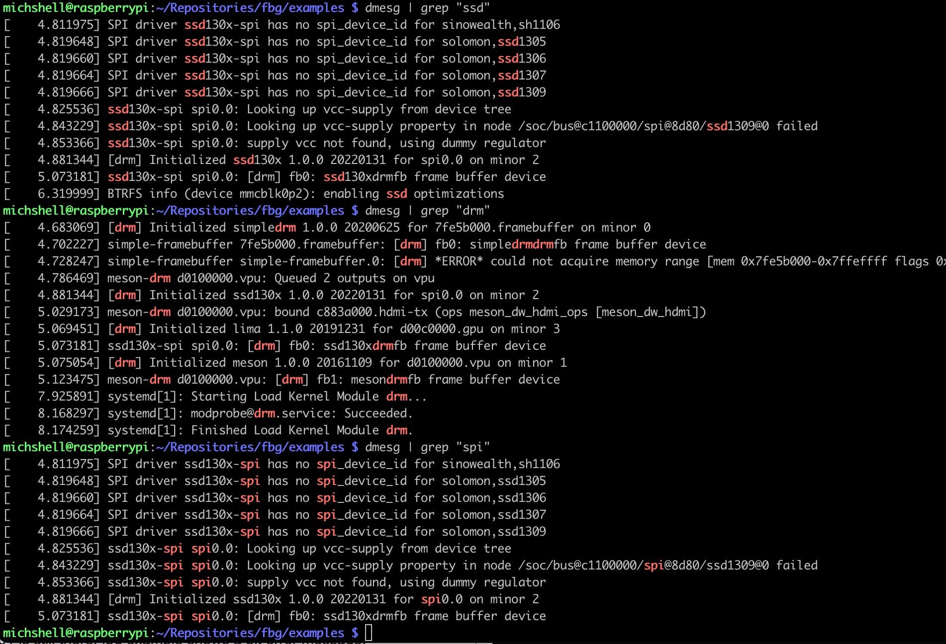
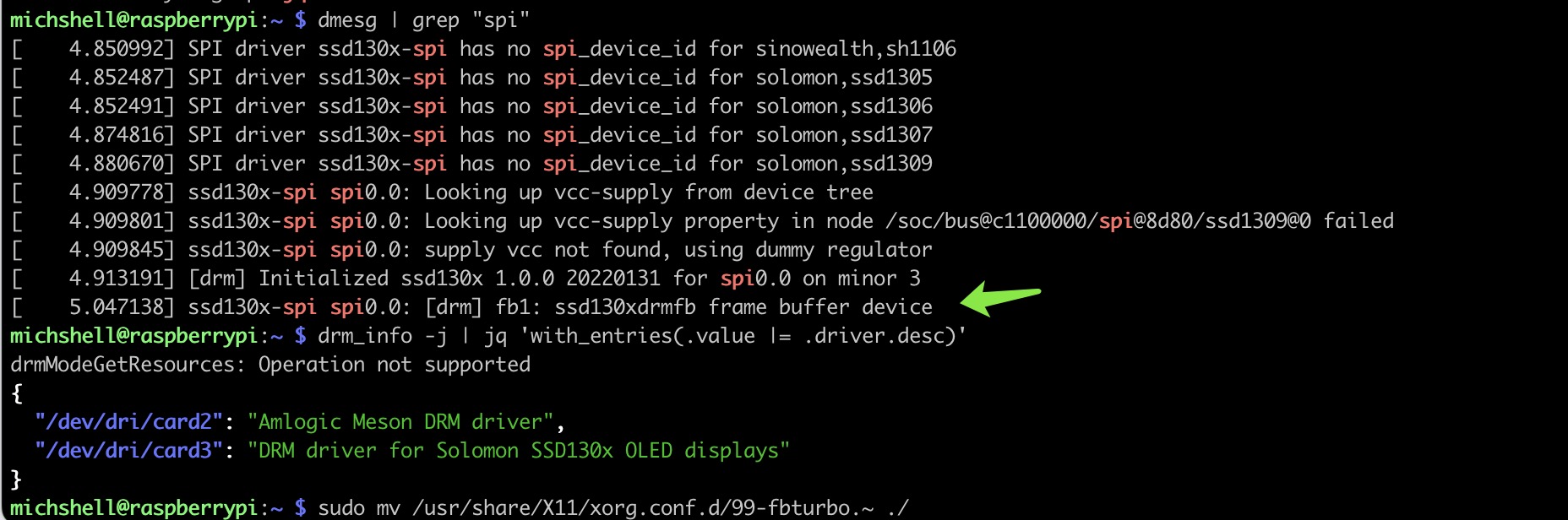
I simply tried to get my plain oled SSD1309 work these days. After lots of struggles I encountered the error " [Errno 16] Device or resource busy", and after googled a while I found a few people complain the similar things, such as,
OSError running sample script for MCP3008 on Libre Computer aml-s905x-cc "Le Potato" · Issue #681 · adafruit/Adafruit_Blinka · GitHub or,
[Errno 16] Opening input line handle: Device or resource busy · Issue #188 · kantlivelong/OctoPrint-PSUControl · GitHub.

Below is one of the code snippets I tried and the error message. Basically I’m trying different python packages and all of them pop out the same error message.

import adafruit_ssd1306
import board
import busio
import digitalio
import time
from PIL import Image, ImageDraw, ImageFont

WIDTH = 128
HEIGHT = 64
BORDER = 5

#spi = busio.SPI(board.SCK, MOSI=board.MOSI)
spi = busio.SPI(board.P23,MOSI=board.P19)
#reset_pin = digitalio.DigitalInOut(board.D17)
reset_pin = digitalio.DigitalInOut(board.P18)
#dc_pin = digitalio.DigitalInOut(board.D22)
dc_pin = digitalio.DigitalInOut(board.P22)
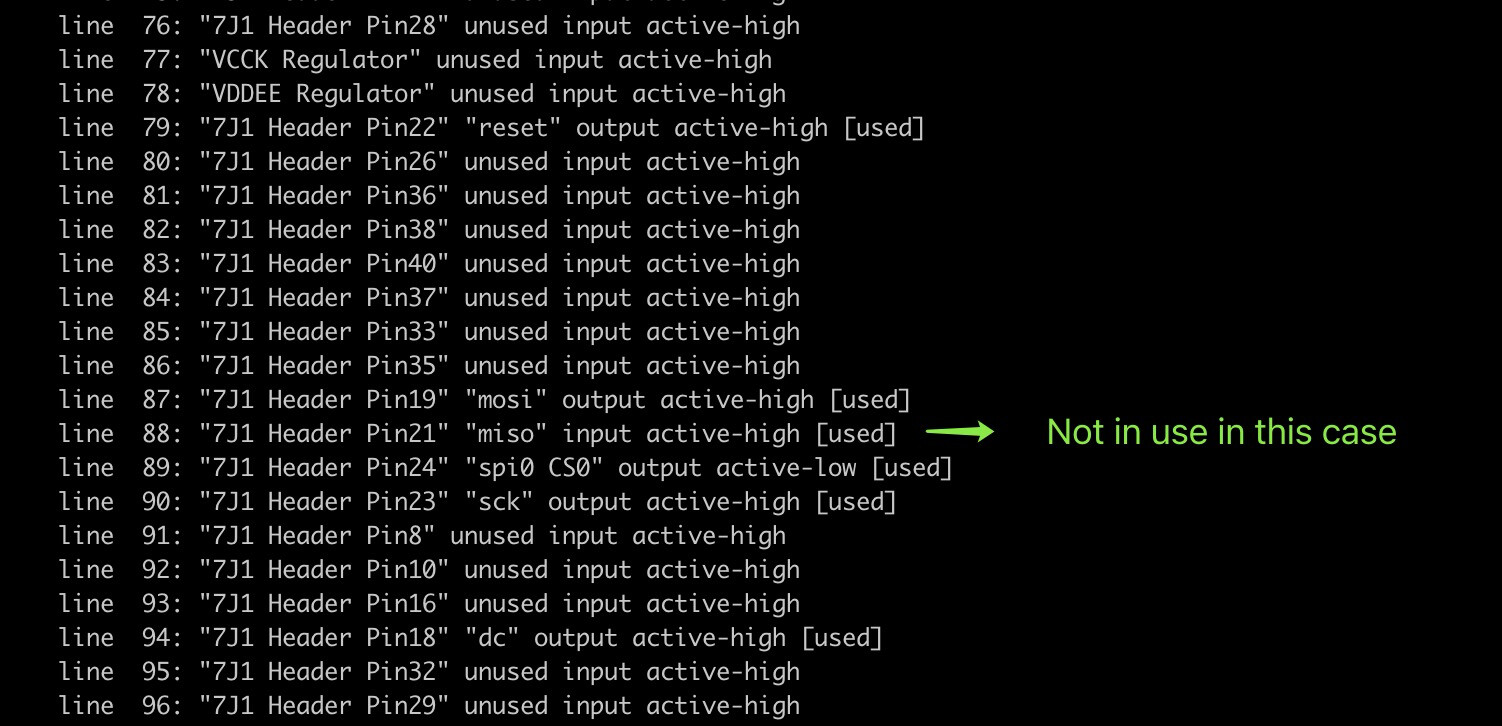
#cs_pin = digitalio.DigitalInOut(board.CE0)
cs_pin = digitalio.DigitalInOut(board.P24)
oled = adafruit_ssd1306.SSD1306_SPI(WIDTH, HEIGHT, spi, dc_pin, reset_pin, cs_pin)
# clean up screen
oled.fill(0)
oled.show()
# blank page
image = Image.new("1", (oled.width, oled.height))
draw = ImageDraw.Draw(image)
draw.rectangle((0, 0, oled.width, oled.height), outline=255, fill=255)
draw.rectangle((BORDER, BORDER, oled.width - BORDER - 1, oled.height - BORDER - 1), fill=0, outline=0)
font = ImageFont.load_default()
text = "Hello World!"
(font_width, font_height) = font.getsize(text)
draw.text(
    (oled.width // 2 - font_width // 2, oled.height // 2 - font_height // 2),
    text,
    font=font,
    fill=255,
)
try:
    while True:
        oled.image(image)
        oled.show()
        time.sleep(3)
except KeyboardInterrupt:
    oled.fill(0)
    oled.show()
Traceback (most recent call last):
  File "/home/michshell/Repositories/SSD1309/busio_ssd1309.py", line 21, in <module>
    cs_pin = digitalio.DigitalInOut(board.P24)
  File "/home/michshell/.local/lib/python3.9/site-packages/digitalio.py", line 165, in __init__
    self.direction = Direction.INPUT
  File "/home/michshell/.local/lib/python3.9/site-packages/digitalio.py", line 195, in direction
    self._pin.init(mode=Pin.IN)
  File "/home/michshell/.local/lib/python3.9/site-packages/adafruit_blinka/microcontroller/generic_linux/libgpiod_pin.py", line 115, in init
    self._line.request(config)
  File "/home/michshell/.local/lib/python3.9/site-packages/gpiod/libgpiodcxx/__init__.py", line 553, in request
    rv = libgpiod.gpiod_line_request(_m_line, conf, default_val)
  File "/home/michshell/.local/lib/python3.9/site-packages/gpiod/libgpiod/__init__.py", line 479, in gpiod_line_request
    return gpiod_line_request_bulk(bulk, config, [default_val])
  File "/home/michshell/.local/lib/python3.9/site-packages/gpiod/libgpiod/__init__.py", line 522, in gpiod_line_request_bulk
    return _line_request_values(bulk, config, default_vals)
  File "/home/michshell/.local/lib/python3.9/site-packages/gpiod/libgpiod/__init__.py", line 387, in _line_request_values
    status = ioctl(fd, GPIO_GET_LINEHANDLE_IOCTL, req)
OSError: [Errno 16] Device or resource busy

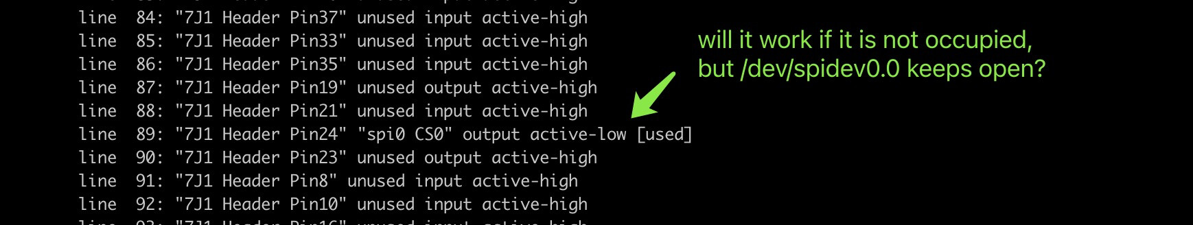
Anyone knows how to lighten up the spi oled in any way?

Hi Michelle,

The first issue you linked to is mine. Blinka does not work with SPI on this board at all, and nobody is really working on it as far as I can tell. Blinka is a bit of a mess, since SBC’s vary widely, and they’re definitely a RPi first type project.

To get the MCP3008 working we had to write a Device Tree Overlay. It was a bit of a learning curve. Here is the thread:

Here’s the driver, you may need to reference it:

I hope that helps get you started.

spi = busio.SPI(board.P23,MOSI=board.P19)
oled = adafruit_ssd1306.SSD1306_SPI(WIDTH, HEIGHT, spi, dc_pin, reset_pin, cs_pin)

Adafruit’s library is designed for Pi only.

SSD1306 is already a supported driver in mainline Linux: drivers/staging/fbtft/fb_ssd1306.c

You just need to write the DT and there are examples in various device trees within the kernel on how it should be written as well as kernel doc on it. You can hook it up via I2C or SPI.

Hello,

I think it is working now, though I don’t know how to test it at the moment.

  1. I found a new device here:

  2. dmesg log looks fine:

My dts file modified based on spicc-ili9486.dts

//file name: ssd1309.dts
/dts-v1/;
/plugin/;

#include <dt-bindings/gpio/gpio.h>
#include <dt-bindings/gpio/meson-gxl-gpio.h>

/ {
	compatible = "libretech,cc", "amlogic,s905x", "amlogic,meson-gxl";

	fragment@0 {
		target = <&spicc>;

		__overlay__ {
			display@0 {
				compatible = "fbtft,fb_ssd1306";
				reg = <0>;
				buswidth = <8>;
				spi-max-frequency = <10000000>;
				reset-gpios = <&gpio GPIOX_0 GPIO_ACTIVE_HIGH>;
				dc-gpios = <&gpio GPIOX_15 GPIO_ACTIVE_HIGH>;
				//num-chipselects = <1>;
				status = "okay";
			};
		};
	};
};

And the ldto cmd is ldto enable spicc ssd1309

fbtft devices should show up as a framebuffer device in /dev/fbX.

Check the driver, the buswidth field should be a Raspberry Pi thing and not necessary.

  1. Yes, one additional /dev/fb1 shown up;
  2. buswidth seem a must, otherwise overlay creation will fail.
1 Like

You should be able to draw on the screen directly.

sudo dd if=/dev/zero of=/dev/fb1
sudo dd if=/dev/urandom of=/dev/fb1

We recommend using OpenGL ES to draw on the framebuffer or some library like this: GitHub - grz0zrg/fbg: Lightweight C 2D graphics API agnostic library with parallelism support

Thanks, admin.

Not working at the moment.
I tried the repo you listed above, the run_quickstart script gets frozen and the code won’t run down.
After that, I even further adapted the dts file, since I’m thinking the below dts structure should be more reasonable than the previous one I posted.
Anyway nothing works at the moment.

current dts file:

/dts-v1/;
/plugin/;

#include <dt-bindings/gpio/gpio.h>
#include <dt-bindings/gpio/meson-gxl-gpio.h>

/ {
	compatible = "libretech,cc", "amlogic,s905x", "amlogic,meson-gxl";

	fragment@0 {
		target = <&spigpio0>;

		__overlay__ {
			display@0 {
				compatible = "fbtft,fb_ssd1306";
				reg = <0>;
				buswidth = <8>;
				//buswidth = <9>;
				spi-max-frequency = <10000000>;
				fps = <30>;
				bgr = <0>;
				txbuflen = <32768>;
				reset-gpios = <&gpio GPIOX_0 GPIO_ACTIVE_HIGH>;
				dc-gpios = <&gpio GPIOX_15 GPIO_ACTIVE_HIGH>;

				//gpio-sck = <&gpio GPIOX_11 GPIO_ACTIVE_HIGH>;
				//gpio-mosi = <&gpio GPIOX_8 GPIO_ACTIVE_HIGH>;
				//gpio-miso = <&gpio GPIOX_9 GPIO_ACTIVE_HIGH>;
				//num-chipselects = <1>;
				status = "okay";
				init = <0x10000ae /* Display Off */
        			0x10000d5 0x80 /* Clock Div */
        			0x10000a8 0x3f /* Set multiplex */
        			0x10000d3 0x00 /* Set Display Offset */
        			0x1000040 /* Set Display Start Line */
        			0x100008d 0x14 /* Charge Pump */
        			0x1000020 0x00 /* Set memory mode */
        			0x10000a1 /* SegRemap */
        			0x10000c8 /* COM Output Scan Direction */
        			0x10000da 0x12 /* Set COM Pins Hardware Conf */
        			0x1000081 0xcf /* Set Contrast */
        			0x10000d9 0xf1 /* Precharge */
        			0x10000db 0x40 /* vcomh */
        			0x10000a4 /* Display All ON and Resume to RAM  */
        			0x10000a6 /* Normal Display */
        			0x10000af /* Set Sleep Mode Display On */
        			>;
			};
		};
	};
};

current dmesg log and gpioinfo:


I tried many examples in both c and python lang, as well as the simple cmd. The screen is just dark.
Below is the fbg result:

The new dts is not correct.

  1. You changed the target from spicc to spigpio0. Why?
  2. The previous compatible is wrong. The DRM-based driver is here: https://github.com/torvalds/linux/blob/master/drivers/gpu/drm/solomon/ssd130x-spi.c
  3. Use only fields that the driver uses. All the other stuff is extraneous. https://www.kernel.org/doc/Documentation/devicetree/bindings/display/solomon%2Cssd1307fb.yaml

Based on above comment,

  1. As my understanding is quite superficial, I turned to spigpio because the wires for MOSI pin and etc are wired. I can see I was wrong and no need to change to spigpio, as I verified it by using the other raspberry pi for testing and observed the gpioinfo on that board while the oled was showing pictures.
  2. Got a bit confused, I think both “fbtft,fb_ssd1306” and “solomon,ssd130x-spi” should work. Anyway I tried “solomon,ssd130x-spi” based on your guide, expectedly this time no /dev/fb1, also I don’t see any new devices such as other iio::devices. Lost the clue again…
  3. Thank you. It is very helpful in long term.

In addition, I think the compatible “fbtft,fb_ssd1306” can be pretty close only it is warning fb_1306 as no spi_device_id, I think if I can put it in dts file or the fb_1306.c file, the spi oled should work by using fbg examples or other framebuf code. Any thought?

  1. spigpio is basically using the CPU to bitbang the IO lines to emulate a SPI bus. spicc is actual hardware block handling SPI data transfers. The upside for spigpio is that it’s completely programmable while the downside is that it is slow and tops out at a few hundred Kb/s. The upside for hardware block is that it’s can do dozens of MHz but the downside is the hardware block’s programmability limitations in terms of clock frequency dividiers, timing, and transfer size.
  2. fbtft is the legacy framebuffer interface and the code to drive the display might not even work. the other compatible is using the proper DRM interface which should definitely work provided that the device tree and the SPI hardware block timing is compatible. However, you mentioned you don’t see fb1, do you see anything relevant in dmesg pertaining to framebuffer, fb, drm, or spi? You can grep for those terms and copy the relevant logs here.
1 Like

Thank you, admin.

The most recent dts file.

/dts-v1/;
/plugin/;

#include <dt-bindings/gpio/gpio.h>
#include <dt-bindings/gpio/meson-gxl-gpio.h>

/ {
	compatible = "libretech,cc", "amlogic,s905x", "amlogic,meson-gxl";

	fragment@0 {
		target = <&spicc>;

		__overlay__ {
			#address-cells = <1>;
			#size-cells = <0>;

			ssd1309: ssd1309@0{
				compatible = "solomon,ssd1306";
				reg = <0>;
				buswidth = <8>;
				spi-max-frequency = <10000000>;
				fps = <30>;
				bgr = <0>;
				bpp = <1>;
				debug = <0>;
				reset-gpios = <&gpio GPIOX_0 GPIO_ACTIVE_HIGH>;
				dc-gpios = <&gpio GPIOX_15 GPIO_ACTIVE_HIGH>;
				status = "okay";
				solomon,height = <64>;
				solomon,width = <128>;
				solomon,page-offset = <0>;
			};
		};
	};
};

//I referred to the raspberry pi dts file.
//https://github.com/raspberrypi/linux/blob/74bc238e86e62109c74d8f229dc105bf3818b4a7/arch/arm/boot/dts/overlays/ssd1306-spi-overlay.dts#L51

the ssd130x-spi.ko does exist but in my case a Null pointer would cause segmentation fault. I can recreate the kernel error if needed. However, the ssd1306 module seem suffice, see below logs.

After that, I did ldto merge spicc ssd1309_spi, and the drm initialization changed a bit, see below.

All the testing code snippets are still not working, such as those in fbg repo and the dd if of command.

You have both drivers enabled. fbtft and the drm driver. Reset your overlays and reboot and then merge the overlays since you seem to have enabled two drivers for the same device. Also is there any channel selects? What commands are you using to merge the spicc?

  1. I just reset it one more time. The result is the same;


    Both drm and fbtft are loaded. I think it is done by the module ssd1306.

  2. I use “ldto enable spicc ssd1309_spi” and then “ldto merge spicc ssd1309_spi” and reboot to merge spicc and ssd1309_spi.

  1. You don’t need to do enable. Enable is for dynamically applying the overlay (not permanently). You can merge and then reboot as it is more consistent than enable.
  2. You need to run ldto reset and then reboot. This sets the default tree. If you don’t reboot after reset, you’re still using the current overlayed tree. It is critical to reset and then reboot and then merge or enable.
drivers/staging/fbtft/fb_ssd1306.c:FBTFT_REGISTER_DRIVER(DRVNAME, "solomon,ssd1306", &display);

It seems both compatibles are the same. You need to blacklist the fb_ssd1306 driver so it doesn’t get probed.

I did as you pointed out.

I did it by adding blacklist-fb_ssd1306.conf under /etc/modprobe.d/. After reset enable merge reboot, fb_ssd1306 is not loaded. /dev/fb1 is still there. fbg example shows a bit error message.
Still I cannot have oled display anything. Have run all the previously mentioned scripts and cmdlines all over again.

Some reboot backlog,

EDIT: I still think the warning “SPI driver ssd130x-spi has no spi_device_id” in the dmesg log is the major problem.

It’s fb0, not fb1 per the dmesg log. Run sudo dd if=/dev/random of=/dev/fb0 to see if the display changes.

Thank you for the reminder. I did NOT notice that. But, fb number varies.
Even after making sure the correct fb* as the output, all scripts still don’t work.

It seems another way to make it work is to write some c testing script by including the ssd1306 lib. I will keep working on it for a while since ssd130x oled is quite common in usage, and hope I can get it over eventually.

Did the command cause we indicated cause the screen to change? Ignore your script for a second.