Firmware update unclear

Hi, I have my AML-A311D-CC-V1.0 board a few days and tried to update the firmware of last 7 januari. I tried it with both SD/USB

  • Flash aml-a311d-cc-spiflash to SD/USB
  • Put it into/Connect to board
  • Power up
    Nothings happens. No HDMI output.

I have the following questions:

  • Could you provide a step for step description for a firmware update?
  • How can you see that an update succeeds?
  • How can you see the version of the current installed firmware?
  • Is it necessary to use the mmc/spi switch on the board?

Are you trying to update the firmware or put an OS onto the SD card and boot the microcontroller (MC) into a OS?

Let’s say you really have updated the firmware that is on the MC, you’ll still want to have a OS on a SD card for booting.

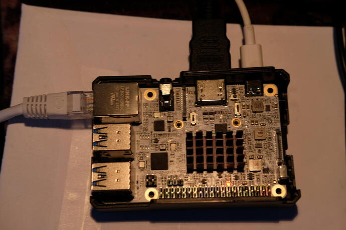
You say the screen is just blank? Post an image of your MC all connected up and not working.

Thank you for your reaction.

Are you trying to update the firmware or put an OS onto the SD card and boot the microcontroller (MC) into a OS?

The question is about the firmware although booting debian base or debian gnome went fine.

Let’s say you really have updated the firmware that is on the MC, you’ll still want to have a OS on a SD card for booting.

Yes, after trying to update the firmware the OS booted ok.

You say the screen is just blank? Post an image of your MC all connected up and not working.

The screen gives a message no signal. When an OS is booted it only shows the linux kernel messages and no u-boot messages.

Hi, I looked further into this.

I connected a serial to USB device and was able to analyse the console output. With this I saw that the firmware update U-Boot 2024.01 from 7 january was flashed successfully. Probably something is wrong with U-Boot detecting the HDMI Display.

Summary

  1. Flash SD or Flash USB with Firmware of U-Boot version.
  2. Load SD Card or USB Stick into SBC
  3. Power up
  4. SBC processes Firmware

Choice SD or Flash USB
My view:
The SBC handles the Firmware as if booting a OS, in this case a flash program. You have to take care that the SBC boots the SD/USB Firmware first.

Note that the SBC will default boot the EMMC, SD before USB.

How to see the firmware version

  1. The version can be seen in the firmware. Finding the version in this application is not optimal.
    hexdump -C u-boot.bin | less and search for 2024.01.
....
000e2050  8c 01 b5 83 03 0b 00 32  63 6c 6b 55 15 04 35 20  |.......2clkU..5 |
000e2060  00 9b 00 10 6c b9 27 03  67 0d 03 cb 21 b4 0d 7c  |....l.'.g...!..||
000e2070  00 0d 2f 00 0d 2d 00 0d  5c 98 0b 03 17 c8 f0 05  |../..-..\.......|
000e2080  00 32 30 32 34 2e 30 31  2d 72 63 36 2b 00 30 31  |.2024.01-rc6+.01|
000e2090  2f 30 31 2f 13 00 13 00  01 a5 14 00 55 ce 90 6b  |/01/........U..k|
...
  1. After the firmware update the SBC shows the firmware version in the console when booting.
    U-Boot 2024.01-rc6+ (Jan 07 2024 - 18:42:47 -0500) Libre Computer AML-A311D-CC

  2. The version can be seen in github setting the relevant branch 2024.01:
    GitHub - libre-computer-project/libretech-u-boot at v2024.01/lc-aml-a311d-cc
    This is still derived information, because you are not sure if the firmware file relates to this branch.
    I would rename the firmware file adding the firmware file.

  3. During updating the Firmware the SBC does not show the version.

** Updating Firmware in SBC**
The console shows the following, I am not sure on which point it started:

SPIFC driver bound
SF: Detected gd25lq128 with page size 256 Bytes, erase size 4 KiB, total 16 MiB
SPI NOR found
20 bytes read in 1 ms (19.5 KiB/s)
Firmware checksum loaded
1031536 bytes read in 55 ms (17.9 MiB/s)
Firmware loaded
Checksum verified
device 0 offset 0x0, size 0xfbd70
0 bytes written, 1031536 bytes skipped in 0.226s, speed 4653272 B/s
Firmware updated
device 0 offset 0x0, size 0xfbd70
SF: 1031536 bytes @ 0x0 Read: OK
Firmware read
Firmware checksum match
Flash Completed

Hardware SPI/SD switch

For the hardware SPI/SD switch question, it seems to have no function or relation with the firmware. So I keep it in the position SD.

The hardware SPI/SD switch controls where the bootloader is searched for. The UEFI firmware we provide is flashed onto SPI. If you have a custom bootloader, you can disable the SPI boot and the board will try to read from the SD card or eMMC.

Previously I talked about the SPI/SD switch (4SW1) but that is on the board labeled with the “SPI MMC”. It is located on the right hand corner, in the picture I sent, in the trangle HDMI, USB C and SOC.

If the switch is set on MMC, towards the SOC, it boots fine. If the switch is on SPI, towards the reset button, it does not boot. The console shows then some output which repeats itself:

G12B:BL:6e7c85:2a3b91;FEAT:E0F83180:402000;POC:F;RCY:0;EMMC:0;READ:0;CHK:1F;READ:0;CHK:1F;READ:0;CHK:1F;SD?:0;SD:0;READ:0;CHK:1F;USB:8;G12B:BL:6e7c85:2a3b91;FEAT:E0F83180:402000;POC:F;RCY:0;EMMC:0;READ:0;CHK:1F;READ:0;CHK:1F;READ:0;CHK:1F;SD?:0;SD:0;READ:0;CHK:1F;USB:8;G12B:BL:6e7c85:2a3b91;FEAT:E0F83180:402000;POC:F;RCY:0;EMMC:0;READ:0;CHK:1F;READ:0;CHK:1F;READ:0;CHK:1F;SD?:0;SD:0;READ:0;CHK:1F;USB:8;▒G12B:BL:6e7c85:2a3b91;FEAT:E0F83180:402000;POC:F;RCY:0;EMMC:0;READ:0;CHK:1F;READ:0;CHK:1F;READ:0;CHK:1F;SD?:0;SD:0;READ:0;CHK:1F;USB:8;G12B:BL:6e7c85:2a3b91;FEAT:E0F83180:402000;POC:F;RCY:0;EMMC:0;READ:0;CHK:1F;READ:0;CHK:1F;READ:0;CHK:1F;SD?:0;SD:0;READ
...

I can go with the explanation of librecomputer that the UEFI firmware is flashed onto SPI but the SPI/MMC switch itself seems to be working the way around.

On this particular board revision, it’s a disable switch, not a selection switch.

I’ve run into the same/similar problem. After running the original firmware for a couple of days successfully with Debian 12, I’ve updated to the latest firmware as instructed on the TensorFlow page (3095) to try those exercises.

The board id is AML-A311D-CC-V1.0C. I flashed via USB and that completed successfully (“Flash Completed”). The flash was https://boot.libre.computer/ci/aml-a311d-cc-spiflash and is dated 2024-Jan-24.

However now it fails to boot. Only a solid red light comes on and there is no output to HDMI. Also, there is no access to the USB drive (it normally flashes when being accessed). I’ve tried the sd card and usb drive (separately).

Any suggested next steps?

Per your boot log, it never tries to boot from SPI. It means your boot switch is in the wrong position.

That answer appears to be for hans311. However, I did try all 4 states of the switches with no change.

Console loops on with the following when booting:
G12B:BL:6e7c85:2a3b91;FEAT:E0F83180:402000;POC:B;RCY:0;SPINOR:0;0.
bl2_stage_init 0x01
bl2_stage_init 0x81
hw id: 0x0000 - pwm id 0x01
bl2_stage_init 0xc1
bl2_stage_init 0x02

L0:00000000
L1:20000703
L2:00008067
L3:14000000
S1:00000000
B2:00402000
B1:e0f83180

TE: 59261

BL2 Built : 15:21:48, Aug 28 2019. g12a g1bf2b53 - luan.yuan@droid15-sz

Board ID = 1
Set cpu clk to 24M
Set clk81 to 24M

Reflash the SPI by flashing the spiflash image to a MicroSD card and moving the boot switch to the other position. This will not use the SPI bootloader but rather the SD card bootloader from the spiflash image.

Thanks. I have gotten it working. But it was not quite as easy as that to do it. I wanted to document it here so that it might be of help to others. Note that I wound up doing this a lot of times and in different ways, so this listing is what I think worked.

  1. Use the Libre flash tool to create a bootable SD card. GitHub - libre-computer-project/libretech-flash-tool The documentation does not list the A311D, but it is there.
  2. Update a USB drive to have the firmware wanted. Libre Computer Board BIOS/Firmware Update Images (see below)
  3. Insert SD card and usb drive
  4. Set the switch to SPI mode (see below – not 100% sure on this. You may have to try both ways)
  5. Turn on the computer and it should update the flash.
  6. Turn off when completely done.
  7. Set the switch to MMC mode and insert fresh OS in the SD slot.

The above is the “happy path”, but I ran into a lot of issues around it. Fully admit these could be me:

  1. SPI vs MMC switch. At least in my mind the switch is labeled backward or confusing. When booting from the SPI flash it is set to MMC (normal mode – 100% sure) and when booting directly from the SD card it is set to SPI (I think, but pretty sure). Perhaps test this [Libre] and change it around on the board or provide a page to document it. The way I read the current documentation (which makes sense) is that SPI mode boots from SPI flash and MMC mode boots from the SD or MMC (maybe also change that name to SD/MMC). While at it, test the press switch which is supposed to boot from USB.
  2. The next issue I ran into was that it would not reflash. It would read the flash on the computer and validate the checksum with the USB and, being the same, call it good without changing it. I tried multiple USBs and multiple downloads. In the end the two flashes were the same, but still not working. Sooo (use at your own risk), being stuck, I flashed the version for the preproduction. Success – sort of. It was able to boot off of SPI now, but it failed to load the OS properly (no surprise). So now I went back and did it one more time with the latest flash and this time it did load it and worked (?). No clue why. This was the same as was loaded before. [Libre] I suggest providing an archive of at least the last couple of revisions so one can rollback if there is an issue with the current version. The site above only lists the latest. I don’t consider flashing for a preproduction board a best practice.
  3. One remaining issues is that after doing an OS update and rebooting, it no longer auto boots into the OS (it did the first time). I have to type “boot”. Most likely a setting to add, but that is for another day.

Hi itb,
It is an interesting story that you need two devices with firmware to boot. Is it possible to share the output of the booting log from the console if the boot is successfull?

Sure.
The two devices are only needed to do the reflash since it would not boot. Now that the flash is redone. It boots fine from the onboard SPI flash to the OS in the SD slot. Here is the console log:

G12B:BL:6e7c85:2a3b91;FEAT:E0F83180:402000;POC:B;RCY:0;SPINOR:0;0.
bl2_stage_init 0x01
bl2_stage_init 0x81
hw id: 0x0000 - pwm id 0x01
bl2_stage_init 0xc1
bl2_stage_init 0x02

L0:00000000
L1:20000703
L2:00008067
L3:14000000
B2:00402000
B1:e0f83180

TE: 58159

BL2 Built : 15:22:05, Aug 28 2019. g12b g1bf2b53 - luan.yuan@droid15-sz

Board ID = 1
Set A53 clk to 24M
Set A73 clk to 24M
Set clk81 to 24M
A53 clk: 1200 MHz
A73 clk: 1200 MHz
CLK81: 166.6M
smccc: 00012ab5
DDR driver_vesion: LPDDR4_PHY_V_0_1_18 build time: Aug 28 2019 15:22:01
board id: 1
Load FIP HDR from SPI, src: 0x00010000, des: 0xfffd0000, size: 0x00004000, part: 0
fw parse done
Load ddrfw from SPI, src: 0x00030000, des: 0xfffd0000, size: 0x0000c000, part: 0
Load ddrfw from SPI, src: 0x00014000, des: 0xfffd0000, size: 0x00004000, part: 0
PIEI prepare done
fastboot data load
fastboot data verify
verify result: 266
Cfg max: 1, cur: 1. Board id: 255. Force loop cfg
LPDDR4 probe
ddr clk to 1584MHz
Load ddrfw from SPI, src: 0x00018000, des: 0xfffd0000, size: 0x0000c000, part: 0

dmc_version 0001
Check phy result
INFO : End of CA training
INFO : End of initialization
INFO : Training has run successfully!
Check phy result
INFO : End of initialization
INFO : End of read enable training
INFO : End of fine write leveling
INFO : End of Write leveling coarse delay
INFO : Training has run successfully!
Check phy result
INFO : End of initialization
INFO : End of read dq deskew training
INFO : End of MPR read delay center optimization
INFO : End of write delay center optimization
INFO : End of read delay center optimization
INFO : End of max read latency training
INFO : Training has run successfully!
1D training succeed
Load ddrfw from SPI, src: 0x00024000, des: 0xfffd0000, size: 0x0000c000, part: 0
Check phy result
INFO : End of initialization
INFO : End of 2D read delay Voltage center optimization
INFO : End of 2D write delay Voltage center optimization
INFO : Training has run successfully!

channel==0
RxClkDly_Margin_A0==98 ps 10
TxDqDly_Margin_A0==98 ps 10
RxClkDly_Margin_A1==98 ps 10
TxDqDly_Margin_A1==108 ps 11
TrainedVREFDQ_A0==74
TrainedVREFDQ_A1==74
VrefDac_Margin_A0==25
DeviceVref_Margin_A0==40
VrefDac_Margin_A1==25
DeviceVref_Margin_A1==40

channel==1
RxClkDly_Margin_A0==88 ps 9
TxDqDly_Margin_A0==98 ps 10
RxClkDly_Margin_A1==88 ps 9
TxDqDly_Margin_A1==98 ps 10
TrainedVREFDQ_A0==77
TrainedVREFDQ_A1==77
VrefDac_Margin_A0==24
DeviceVref_Margin_A0==37
VrefDac_Margin_A1==22
DeviceVref_Margin_A1==37

dwc_ddrphy_apb_wr((0<<20)|(2<<16)|(0<<12)|(0xb0):0004

soc_vref_reg_value 0x 00000018 00000017 00000017 00000016 00000019 00000016 00000018 00000018 00000017 00000018 00000017 00000018 00000016 00000018 00000017 00000018 00000017 00000018 00000019 00000017 00000017 00000017 00000016 00000016 00000018 00000017 00000019 00000017 00000019 00000016 00000017 00000017 dram_vref_reg_value 0x 0000005f
2D training succeed
aml_ddr_fw_vesion: LPDDR4_PHY_V_0_1_18 build time: Aug 28 2019 13:54:19
auto size-- 65535DDR cs0 size: 2048MB
DDR cs1 size: 2048MB
DMC_DDR_CTRL: 00e00024DDR size: 3928MB
cs0 DataBus test pass
cs1 DataBus test pass
cs0 AddrBus test pass
cs1 AddrBus test pass

100bdlr_step_size ps== 432
result report
boot times 0Enable ddr reg access
Load FIP HDR from SPI, src: 0x00010000, des: 0x01700000, size: 0x00004000, part: 0
Load BL3X from SPI, src: 0x0003c000, des: 0x0172c000, size: 0x000c4000, part: 0
0.0;M3 CHK:0;cm4_sp_mode 0
MVN_1=0x00000000
MVN_2=0x00000000
[Image: g12b_v1.1.3390-6ac5299 2019-09-26 14:10:05 luan.yuan@droid15-sz]
OPS=0x10
ring efuse init
chipver efuse init
29 0b 10 00 01 14 25 00 00 11 38 33 33 42 42 50
[0.018960 Inits done]
secure task start!
high task start!
low task start!
run into bl31
NOTICE: BL31: v1.3(release):4fc40b1
NOTICE: BL31: Built : 15:58:17, May 22 2019
NOTICE: BL31: G12A normal boot!
NOTICE: BL31: BL33 decompress pass
ERROR: Error initializing runtime service opteed_fast

U-Boot 2024.01+ (Jan 24 2024 - 00:10:13 -0500) Libre Computer AML-A311D-CC

Model: Libre Computer AML-A311D-CC Alta
SoC: Amlogic Meson G12B (A311D) Revision 29:b (10:2)
DRAM: 2 GiB (effective 3.8 GiB)
Core: 408 devices, 31 uclasses, devicetree: separate
WDT: Not starting watchdog@f0d0
MMC: mmc@ffe05000: 1, mmc@ffe07000: 0
Loading Environment from FAT… Card did not respond to voltage select! : -110
** Bad device specification mmc 0 **
Card did not respond to voltage select! : -110
** Bad device specification mmc 0 **
Couldn’t find partition mmc 0
Card did not respond to voltage select! : -110
** Bad device specification mmc 0 **
Couldn’t find partition mmc 0
Error: could not access storage.
Net: eth0: ethernet@ff3f0000
starting USB…
Bus usb@ff500000: Register 3000140 NbrPorts 3
Starting the controller
USB XHCI 1.10
scanning bus usb@ff500000 for devices… 6 USB Device(s) found
scanning usb for storage devices… 0 Storage Device(s) found
Hit any key to stop autoboot: 0
Scanning for bootflows in all bootdevs
Seq Method State Uclass Part Name Filename


Scanning global bootmeth ‘efi_mgr’:
Card did not respond to voltage select! : -110
Scanning bootdev ‘mmc@ffe07000.bootdev’:
Card did not respond to voltage select! : -110
Scanning bootdev ‘mmc@ffe05000.bootdev’:
0 efi ready mmc 1 mmc@ffe05000.bootdev.part efi/boot/bootaa64.efi
** Booting bootflow ‘mmc@ffe05000.bootdev.part_1’ with efi
Booting /efi\boot\bootaa64.efi
Welcome to GRUB!
Hi itb,

Thanks, I compared it to my console log. The last part is almost the same. I have got an emmc, device mmc 0. The firmware can’t find the mmc 0 device on your board. Hence the difference.

U-Boot 2024.01+ (Jan 24 2024 - 00:10:13 -0500) Libre Computer AML-A311D-CC

Model: Libre Computer AML-A311D-CC Alta
SoC:   Amlogic Meson G12B (A311D) Revision 29:b (10:2)
DRAM:  2 GiB (effective 3.8 GiB)
Core:  408 devices, 31 uclasses, devicetree: separate
WDT:   Not starting watchdog@f0d0
MMC:   mmc@ffe05000: 1, mmc@ffe07000: 0
Loading Environment from FAT... ** No valid partitions found **
** Invalid partition 1 **
Couldn't find partition mmc 0
** Invalid partition 1 **
Couldn't find partition mmc 0
Error: could not access storage.
Net:   eth0: ethernet@ff3f0000
starting USB...
Bus usb@ff500000: Register 3000140 NbrPorts 3
Starting the controller
USB XHCI 1.10
scanning bus usb@ff500000 for devices... 4 USB Device(s) found
       scanning usb for storage devices... 0 Storage Device(s) found
Hit any key to stop autoboot:  1  0 
Scanning for bootflows in all bootdevs
Seq  Method       State   Uclass    Part  Name                      Filename
---  -----------  ------  --------  ----  ------------------------  ----------------
Scanning global bootmeth 'efi_mgr':
Scanning bootdev 'mmc@ffe07000.bootdev':
Scanning bootdev 'mmc@ffe05000.bootdev':
  0  efi          ready   mmc          1  mmc@ffe05000.bootdev.part efi/boot/bootaa64.efi
** Booting bootflow 'mmc@ffe05000.bootdev.part_1' with efi
Booting /efi\boot\bootaa64.efi