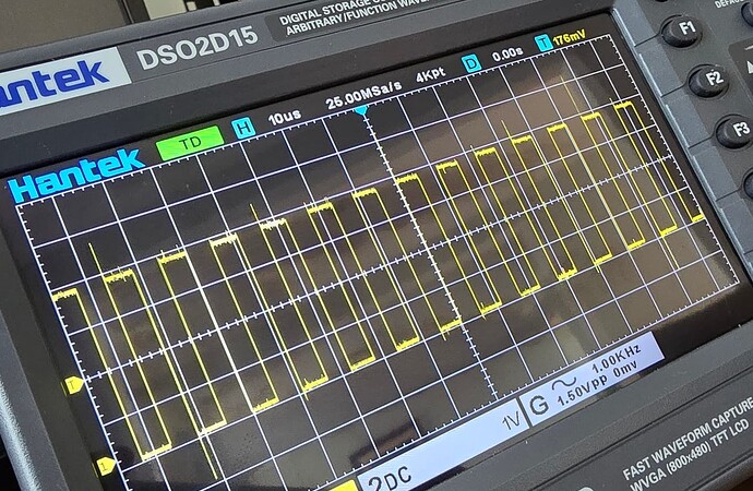
Also see PWM Fan Control Guide
There are 10 PWMs, 4 AO and 6 EE. Any GPIO can be used as a software PWM but those require CPU interrupts which are taxing for the system and not as accurate. These are the pins that can be muxed to expose PWM functionality. For graphical representation, see the GPIO header maps.
PWM to GPIO pinmux
- PWMAO_A GPIOAO_11
- PWMAO_B GPIOE_0
- PWMAO_C GPIOAO_4 GPIOAO_6
- PWMAO_D GPIOE_1 GPIOAO_5 GPIOAO_10
- PWM_A GPIOX_6
- PWM_B GPIOZ_0 GPIOZ_13 GPIOX_7 GPIOX_19 GPIOH_7
- PWM_C GPIOX_8 GPIOX_5 GPIOC_4 GPIOZ_1
- PWM_D GPIOZ_2 GPIOA_4 GPIOX_3 GPIOX_6
- PWM_E GPIOX_16
- PWM_F GPIOX_7 GPIOH_5 GPIOZ_12 GPIOA_11
Header Pin to PWM pinmux
- Pin 7 - PWMAO_C GPIOAO_6 pwm-ao-c-6
- Pin 16 - PWM_D GPIOA_4 Please Request Below, by default used by Green LED
- Pin 21 - PWM_F GPIOH_5 pwm-f-h5
- Pin 23 - PWM_B GPIOH_7 Please Request Below, by default used by Blue LED
- Pin 32 - PWM_F GPIOA_11 pwm-f-a11
- Pin 33 - PWM_C GPIOX_5 pwm-c-x5
- Pin 38 - PWM_C GPIOX_8 pwm-c-x8
Some of the PWMs are already used for CPU voltage regulation per the schematics and cannot be changed without crashing the system but the PWMs on the headers should all be available.
Amlogic PWMs are paired meaning that a single module controls two PWMs so care must be taken in layering the device tree overlays. For example, AB are paired, CD are paired, etc. You cannot enable pwm-a and then enable pwm-b. You have to enable pwm-ab.
The Linux kernel interface can be accessed via sysfs.
sudo ldto enable pwm-{x} # replace x with one of the dtos in list above
ls -al /sys/class/pwm # see the pwmchip{n} to hardware mapping
echo {0,1} | sudo tee /sys/class/pwm/pwmchip{n}/export # 0 for a/c/e, 1 for b/d/f
echo 1000000 | sudo tee /sys/class/pwm/pwmchip{n}/pwm{n}/period
echo 500000 | sudo tee /sys/class/pwm/pwmchip{n}/pwm{n}/duty_cycle
echo 1 | sudo tee /sys/class/pwm/pwmchip{n}/pwm{n}/enable
PWM chip numbers can be determined by matching the pwm_AO_cd, pwm_ab, pwm_cd, pwm_ef node paths from the Alta or Solitude device-tree to the node paths in /sys/class/pwm. Below is an example, but please run it on your system to determine the active mapping as they may not match below.
$ ls -al /sys/class/pwm
total 0
drwxr-xr-x  2 root root 0 Dec 31  1969 .
drwxr-xr-x 92 root root 0 Dec 31  1969 ..
lrwxrwxrwx  1 root root 0 Dec 31  1969 pwmchip0 -> ../../devices/platform/soc/ff800000.bus/ff802000.pwm/pwm/pwmchip0
lrwxrwxrwx  1 root root 0 Dec 31  1969 pwmchip1 -> ../../devices/platform/soc/ffd00000.bus/ffd19000.pwm/pwm/pwmchip1
lrwxrwxrwx  1 root root 0 Dec 31  1969 pwmchip2 -> ../../devices/platform/soc/ffd00000.bus/ffd1a000.pwm/pwm/pwmchip2
lrwxrwxrwx  1 root root 0 Dec 31  1969 pwmchip3 -> ../../devices/platform/soc/ffd00000.bus/ffd1b000.pwm/pwm/pwmchip3
