Le Potato: Hanging + whole screen one color

Getting a hanging issue with Le Potato. Wondering if it’s a know thing.

After a while of use my AML-S905X-CC becomes unresponsive/hangs/crashes with the whole screen turning some random color. It DOES appear to happen when I am “doing something intensive”

Power Currently, this is what I suspect the most. I’ve been using a 2.1A USB wall adapter originally for a Nook tablet that has historically worked well for me for high drain USB devices. However, I noted that the thing was “hot” when I last went to unplug it. (I’d estimate something like 65-85c.) I also pondered over the things it was working well for and noted that they were battery operated.This made me theorize that it perhaps briefly shuts down and restarts… and I just never knew because of the specifics. I intend to power via the header using a more attestable supply than an off the shelf USB wall adapter. Refer to this thread for the general idea.

Heat This was the first thing I suspected, but is now less likely IMHO. Only having experience with this form factor on the original RasPi, It never even occurred to me that the main SoC could get very hot. I figured it was a budget SoC designed with handheld power limitations in mind. Plus, it didn’t come with a heatsink. So, it was quite the shock to feel how nuclear hot the main SoC was getting. My knee jerk reaction was “Aaa Haaa! FOUND IT!!” So… I RTV’d some heat sinks on it AND added a fan. No change in issue, but I feel a little better about lowering temps either way. B)

(Slightly tangential, but I certainly hope Amlogic had the common sense to add hardware enforced thermal throttling/shutdown so that skyrocketing temps wouldn’t permanently detonate the SoC. I’d probably want my money back if this most basic safety was absent… Would love some official docs to sleuth this one out. At the very least, Le Potato is commonly supplied without a heatsink, and no warning to add one, so SOMEONE though this was a safe thing to do.)

SD Card I’ve tried different SD cards. Problem exists with at least two different units, name brand and cheap. Currently using a Samsung EVO Select 128GB that tests well and has served me well in my phone for the last ~ 2 years. May drop in my similar 64GB card if I feel it’s a 1 off issue with the card.

OS Image I suspected incompatibility or corruption in the image somewhat possible, so each time I switch my card around I tried a different OS image too. I’ve gone through “ubuntu-22.04.1-preinstalled-desktop-arm64+aml-s905x-cc.img.xz”, and “Armbian_23.02.2_Lepotato_jammy_current_6.1.11_xfce_desktop.img.xz” I’m using Rufus 4.0 portable to write images to the card. I’m using an ancient "Transend - Multiple Card Reader USB Device
" (VID_058F & PID_6366) … i.e. just a generic SD card to USB adapter. Image seams to verify, so I doubt it’s a write issue.

I’ll of course report back after I mess with alternative power supply options, but, in case this is a known issue, I’ll ask… Has anyone else had this problem? What was the cause? How did you fix it?

… Please and Thank you.
Hanging without an error message is usually a power issue.

2 Likes

Naturally, this is what I figured too. Thanks for the extra confirmation. Again, I need to come up with something more robust to power this thing before I can confirm our mutual suspicion.

Now… you mention error messages. I will be forthcoming in confessing that I haven’t done my fair bit to search for error messages. Partly because of laziness, and partly because the screen I have for this project is a 38" TV bolted to a wall far far away from my TTL serial to USB adapter and associated paraphernalia. If I don’t strike pay dirt swapping power supplies, I’ll have to find it in myself to do the right thing here.

1 Like

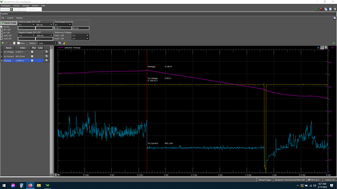
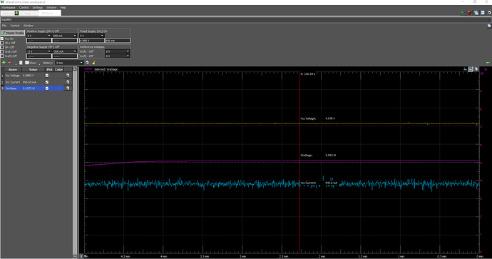
Welp… doesn’t appear to be power supply related. Running off my lab supply with full transient and power tracking and it hasn’t shown any issues, but just now the system locked up. I was running stress-ng when It happened… Screenshot of lab supply metrics…

1 Like

Power is also an issue with the plug. If you can scope the 5V header pins and set a trigger when it drops below 4.7V. If you have an UART line, you can attach and see the last message you get.

2 Likes

As far as heat is concerned:
Heatsink and fan are pretty much required if you’re running a desktop, or in a warm environment. By default, it throttles at 60℃.

Smarter folks than I have discussed this in more detail here:

1 Like

Checking back in.

Since my last post I’ve let the thing run idle on its desktop with sleep disabled … that is I let it stew on the GUI for ~10 hours without any other load. It did not hang. So…I’d like to think it’s confirmed that it is an issue specific to the system being under load. This, of course, does not rule out power supply or thermal issues, but it is useful information.

I need to do some targeted tests on the functional units, to see if the problem happens to be located in any particular section of silicon. The theory is one of the functional units is defective. The testable hypothesis is that, if theory holds, just one functional unit running can cause the hang. This would have the absolute minimal heat and power impact. Specific actionable items would then be, run stress-ng pinned to each core in turn. Then run some OpenGL GPU stress test. Then maybe run some RAM stress tests.

@librecomputer
Power is also an issue with the plug.

If you are referring to the micro USB plug/socket being trash, I’m well aware. It always is. LOL. Thankfully, that isn’t how I’m powering the board right now . I have multiple dupont jumper wires jumping from my supply to the 5V pins and grounds on the GPIO header. I suppose could add a few more just to really put the last nail in that coffin.

@librecomputer
If you can scope the 5V header pins and set a trigger when it drops below 4.7V.

Are you talking about setting it up in a kelvin sensing arrangement? i.e. to look at voltage drop at the point of load? If so, that was going to be my next test TBQH.

@librecomputer
If you have an UART line, you can attach and see the last message you get.

This is priority number one in my mind. I need to see if it throws some kind of error then poops itself, or if it just goes instantly vegetative without even knowing what’s going on. One of these things is not like the other. Useful information.

@angus
As far as heat is concerned:
Heatsink and fan are pretty much required if you’re running a desktop, or in a warm environment. By default, it throttles at 60℃.

Yes, right. Seeing what I have seen now I would agree. I would even go as far as to say at least a passive heatsink is required no matter what. “Mandatory component.”

Mine does indeed have heatsink+fan now and the SoC encapsulation temps aren’t even in the same zip code as 60c. It’s maybe 35c under full load… maybe. No idea what the junction/core temps are, since I have no metrics for that atm.

Here is another screen shot I took the last crash. The red line is the moment of crash. The dip in the yellow trace is me power cycling the board.

… I’m going to be away from the computer for about 8-10 hours again. Something about humans needing sleep eventually. After I’m back among the living, I will see if I can do the above mentioned things.

If you want the quick and dirty solution, just order another board and see if it happens on the second board.

2 Likes

The thought crossed my mind… believe me.

Edit: … Hell with it. Done! … we will see what happens in a few days.

1 Like

If it is still problematic, it’s most likely your setup rather than the board.

You can always return the boards back to where you ordered them and it only costs our distribution $15 in fees so it’s quicker and cheaper than wasting everybody’s time if the board does not behave correctly.

2 Likes

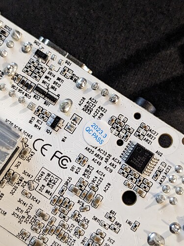
I have to say… It is really going to be quite bothersome if this board was DoA, considering it has a QC pass sticker on it… Someone may have to anticipate having an uncomfortable conversation soon.

1 Like

Our QC includes running every subsystem at maximum speed so we are fairly confident in our boards.

Here’s a list of tests we run to validate:

  1. cpuburn-a53
  2. glmark2
  3. MicroSD and eMMC IO at max
  4. USB throughput
  5. Ethernet throughput
  6. RAM bandwidth and consistency
  7. CPU performance and consistency
  8. IR sensor
  9. HDMI bandwidth test

Nobody in this industry comes close in terms of testing and validation framework. This is one of our core IP components, manufacturing tests.

1 Like

Update. FOUND THE PROBLEM WITH GOOD CONFIDENCE

(TL;DR, Yes, it was the power. Haven’t found SPECIFICALLY what, but it is power related.)

So. While waiting for unit two to arrive I started on doing some of the other things I said I wanted to try.

Today I started messing around with putting a four-terminal sensing (kelvin) arrangement on the board to get a better picture what the board itself is actually seeing voltage wise on what I am just going to call it’s 5V node.

Here is how I set it up…


Arrangement
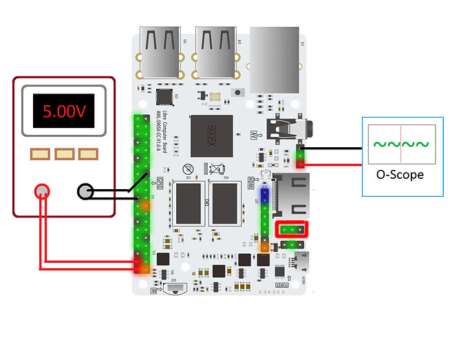
The above image is a quick-and-dirty diagram of my setup for measuring these kinds of things.

(left side) The main power is provided to the board through two (2) Dupont jumper wires in parallel connecting my lab supply positive to both pins 2 and 4 of “40 pin header 7J1.” Two more (2) Dupont jumper wires are connected from my lab supply ground to pins 20 and 25 of the same header. Each wire is good to 1A, so two wires should be able to handle 2A. Supply is set to 5.000V, and measures out to about 4.95-5.05A. Being aware of potential false precision, I measured with two other multimeters and they were in pretty good agreement to this number.

(right side) The kelvin sensing arrangement is achieved by hooking in my O-scope with a totally independent 5V and GND wire pair, attached to pins 3 and 1 of “SPDIF Header 9J1” As can be seen, this puts my tap clear on the other side of the board, giving me the absolute worst case picture of the total voltage drop under load. This gives a birds eye view, which, unfortunately doesn’t inform me if it is my supply, wires, or the PCB routing causing the droop. The ONLY THING this setup can show is if a voltage droop on the 5V node exists or does not exist.

I have been running Glmark2 + stress-ng + some network ops + disk ops to put full load, and consequently, full power draw on the board. . .

Findings

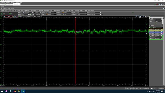
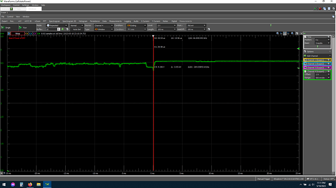
The above image is an o-scope trace where the scope was set to take a capture whenever the voltage gets outside of a window. The window is centered on 5.000V with a 0.680V width (green arrows top, far right). The red line is centered on time T0 or when the voltage was first observed dipping below threshold. Importantly… it currently reads 4.314V. :warning: This is already alarmingly low and, were this not a public thing, I would have just called it right here and corrected the supply problem. However, I wanted a smoking gun for the benefit of all. Critically, the main SoC was still running fully even at these voltages. However, my WiFi adapter would randomly leave the chat, requiring a power cycle to start working again, and I was pretty sure at this point it’s this voltage droop that is to blame. Everything else I felt just needed a little more of a shove to give in…

Following the above line of logic, I decided to remove one wire off the supply side to help coax the system into an even lower sag and a possible hang. Aaaaaand… the results were clockwork! Right at 4.2V the board hangs with a random color filling the screen, and zero responsiveness, exactly what I have been seeing.

The above trace is a capture of the boards 5V node right at the moment of crash. The voltage reads 4.196V. I ran it a few more times to confirm and every time it hung up the voltage had just sagged below 4.2V.

It’s still not “case closed” … but the problem has been clearly identified. I can now reproduce like flipping a switch. This is, of course, excellent news.

The next step I need to do is figure out if my earlier problems are from a poor connection, low voltage supply, both, or if (highly unlikely) the board itself is the source of the voltage drop. I do vaguely recall something about the Raspberry Pi boards basically requiring adapters with slightly higher voltage than precisely 5.000V to compensate for board internal voltage drop, I would like to know if that’s the case with these SBCs as well.

In any case, to everyone’s satisfaction, my board is likely NOT DoA. It is as we had suspected. Inadequate voltage at the 5V node is causing SoC brownout.

This is where a second board comes in handy. You either know that the a transistor on the board is not working properly or the power input is not sufficient.

2 Likes

Final thoughts

So, I got the second board, and also did some final confirmation testing and so on. Here are MY conclusions. . . (of which future readers can take or leave)

Micro USB proves to be the dumpster fire it always has been. In spite of the fact that my USB wall adapter is rock solid, there is just no keeping the voltage up through both typical micro USB cords + the micro USB on the potato. My personal recommendation is to just always power through the 40 pin header.

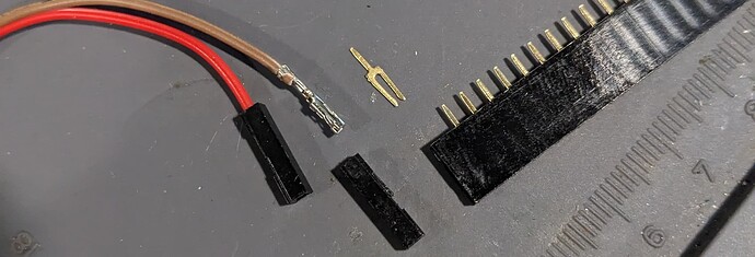
… and about powering though the header. Be sure the connector you are using is high quality and (arguably more importantly) a good design. The style I am using now is a gold plated “pitch fork” type, which is what you will probably only see on through hole PCB headers. The crimp on style, (at least the ones I have) are tin plated thin trash tier design, and have basically zero contact pressure on the header pin. You see these on the end of “jumper wires.” This design is at least 50% the reason I had problems I figured I really shouldn’t have had.

Here is a side by side picture. . .

The left side is what was giving me problems. The type on the right is what is working a million times better. Note that I DID have to solder wires to this. . . May not be the solution for everyone.

That being said, 2x20 female header sockets are a dollar or two on Amazon with next day, can be soldered OFF the Potato board, and can be a good practice for getting your feet wet with soldering. That, OR you can just get a 40 pin terminal block breakout, allowing you to simply use screw terminals and avoid soldering all together, you know, should the thought of molten metal scare you.

Part of the reason I was having problems was that I was “trying too hard” with my voltages. That is to say, I was using a lab supply and making sure the voltages were dead center 5.000V, because, you know, that’s what it’s supposed to be! This over precision proved to be a burden, not an asset however. USB 1.0 specs allow a max of 5.25V, and newer USB 2.0 specs allow up to 5.5V. I would imagine that 98% of USB 1.0 devices (100% of those device that are still relevant) also will handle 5.5V. With that in mind, and observing the fact that all four of the USB ports are powered directly from your supply, I would strongly encourage anyone undertaking this to use 5.25-5.50 volts to power Le Potato… maybe more if you are using the crappy micro USB socket.

The problem is not the MicroUSB connector but rather crappy MicroUSB cables. Some of them are really thin and have high internal resistance since they use thin and low-grade aluminum. Be careful not to exceed 5.5V as a lot of devices will power off and not work. If you use a 500mA USB to MicroUSB cable, it’s not going to hold voltages when you are pushing 1A+ through them.

Our distributors sell proper power supplies with good cables.

“The problem is not the MicroUSB connector but rather crappy MicroUSB cables.”

I respectfully disagree.

Yes, cables are a significant problem, but so too is the connector. USB Micro-B was never specified to handle any more than 1A, and that 1A was only specified because they over provisioned the current by 2X for reliability reasons. Truthfully, it’s only intended for only 500mA, as USB itself was only ever specified up to 500mA.That is until in USB 3.0 when current was bumped to 900mA. (which itself was chosen because it was 100mA lower than the max design limit for already existing connectors, e.g. USB Micro-B.)

On full load I can get to drawing 900-1200mA with just Le Potato… add 4x USB devices, even only 150mA, and you are already asking for problems when powering off MicroUSB. … don’t even think about mid range WiFi adapters or thumb drives with this arrangement. 3A is easily achievable with USB stuff I just happen to have laying around.

Micro USB for power was a bad idea on the original pi, it’s still a bad idea today. This is why USB-C was embraced so strongly, even by trivial to power devices. USB-C connector is good to 3A

“Some [MicroUSB cables] are really thin and have high internal resistance since they use thin and low-grade aluminum.”

I agree cheap MicroUSB cables with CCA wire are trash, and is the cause of many problems. It’s not the only problem though.

“Our distributors sell proper power supplies with good cables.”

Sure! But then why do this when one can instead have a 3A adjustable DC-DC converter module with a PCB about the size of a fingernail for less than $1 each that, when attached directly via the 40 pin header, give better results?

I get about 100mV voltage sag on the 5V node going from idle to full load this way, and I’m sure a large fraction of that is actually voltage drop on the board’s internal power node. A welcome bonus with this setup is that DC-DC converter modules can typically take anywhere from 5-25 volts input.

The one by my bed is plugged into a bog standard 2A@12V wall adapter and is happy as a clam.

MicroUSB was designed for 1.8A with no significant voltage drop. We have boards running at 2.2A 24/7 in the lab on MicroUSB. If it wasn’t sufficient to power our boards, we wouldn’t use it.

You are referring to the USB IF power spec and not the connector design current. You do get some voltage drop at 2.5A (Le Potato with cpuburn-a53 + 2 max draw 500mA peripherals) but it’s not an issue with the correct power supply that supplies 5.1-5.2V at the connector.

Always check the power tree in the schematics. Le Potato is not designed to be powered via 5V on the header since it’s behind a regulator but you can do it without much issue.

I’ve successfully run small a spinning hard-drive, wifi-adapter and charged a phone all at the same time with the board powered over micro USB just to see what it could do. No problems whatsoever, even though I was knowingly pushing my luck. I don’t think this connector is an issue.

1 Like