AML-S905X-CC with GP2Y0A21YK0F IR Distance Sensor

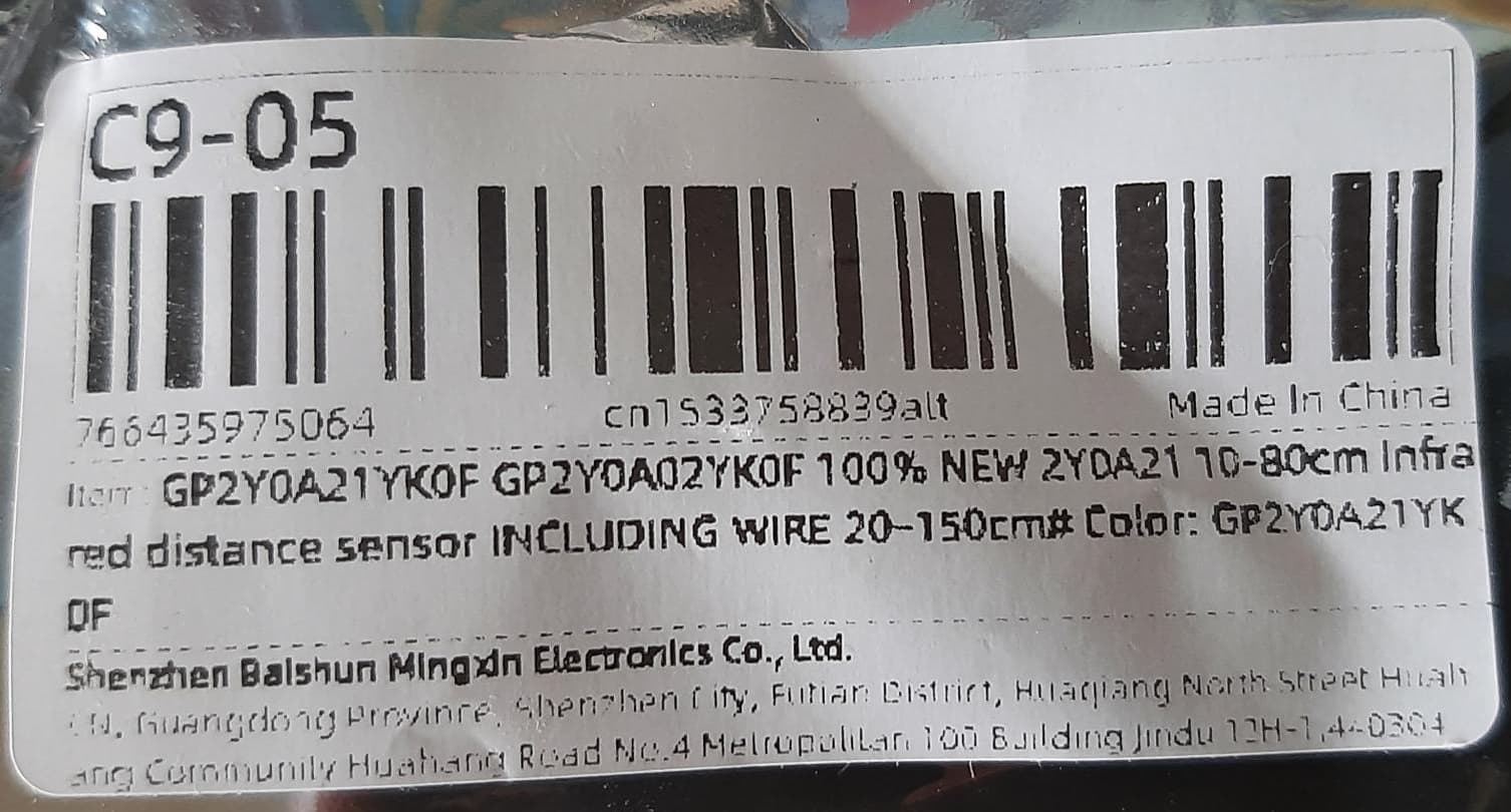
From AliExpress, I’ve purchased a few of the below IR distance sensors.


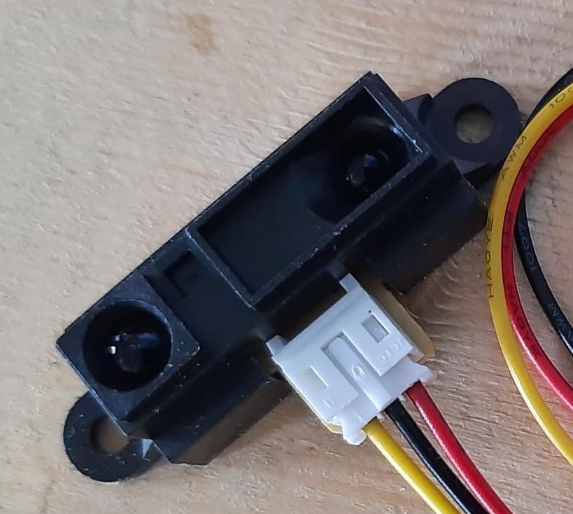
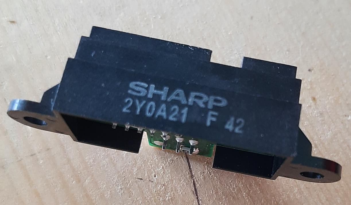
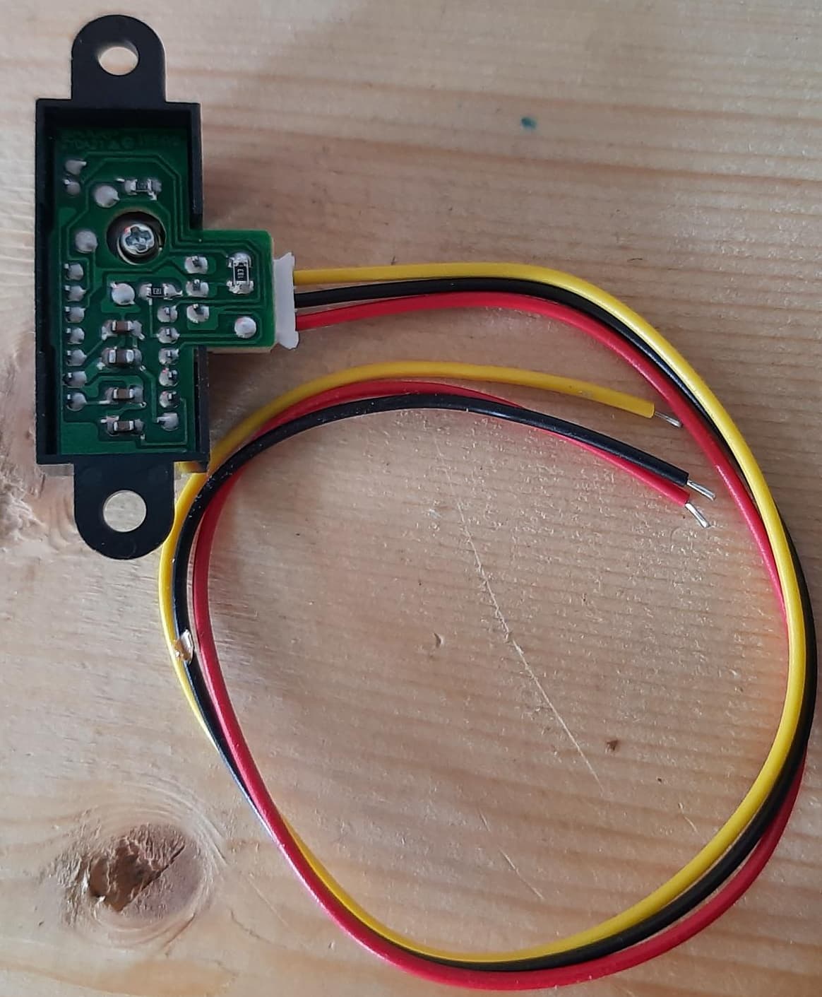
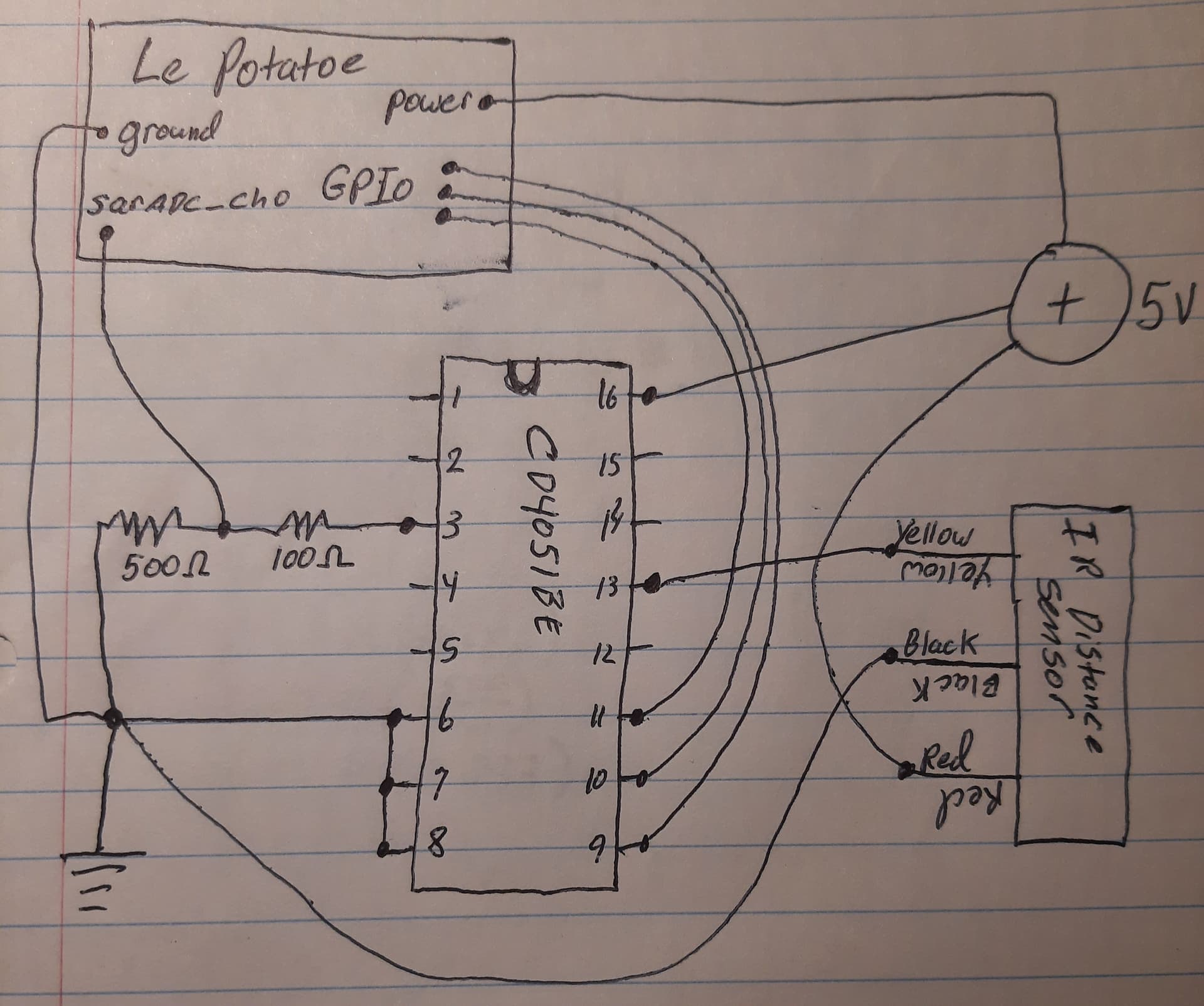
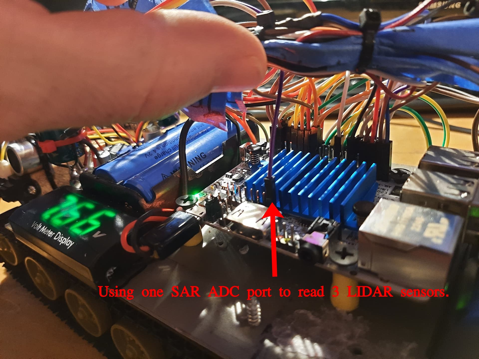
I intend to read the measurements from this device via the AML-S905X-CC.

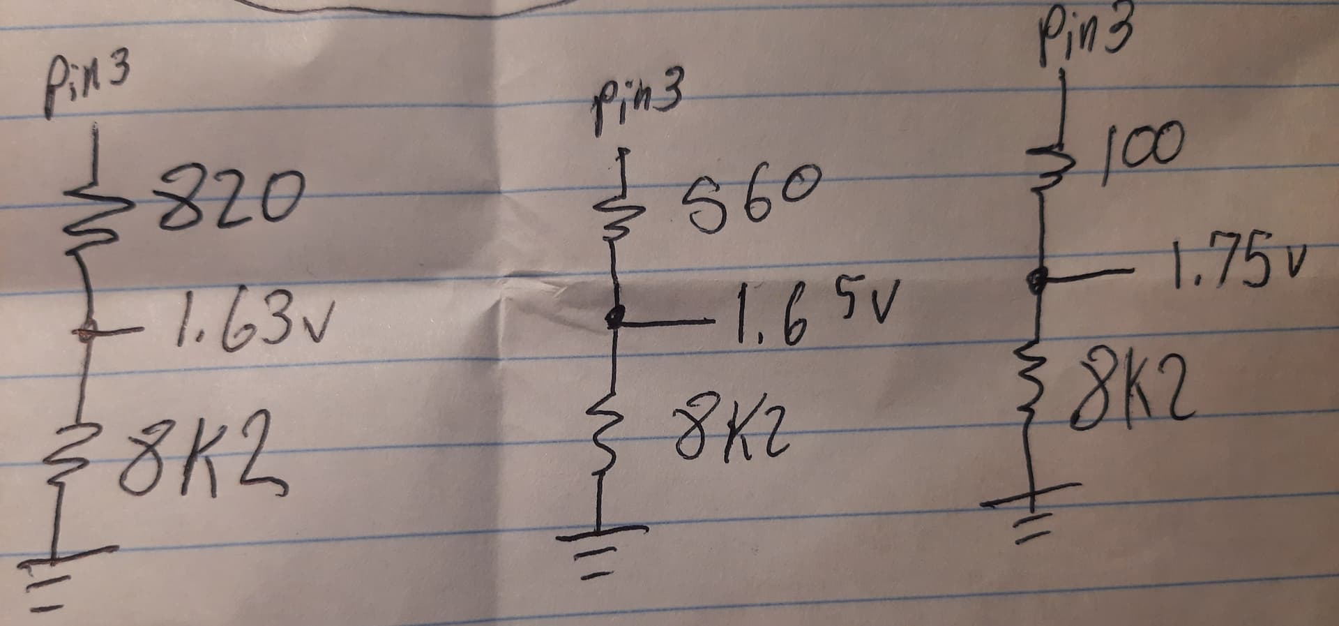
I understand these distance sensors output a DC voltage that represents distance. I’m not sure what my exact model will output, but based on this tutorial I found, the ranges are 0.4v to 3.2v or something like that.

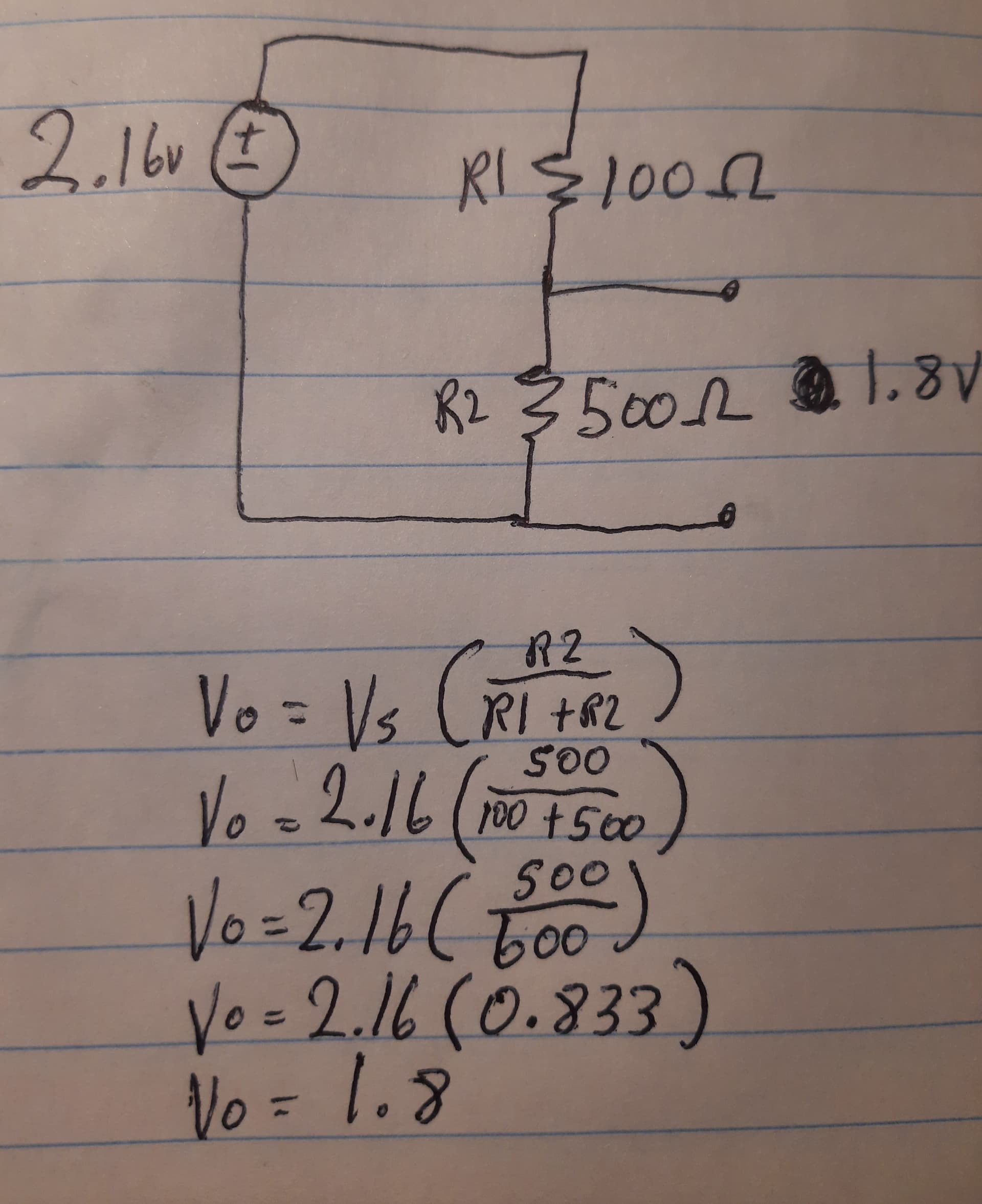
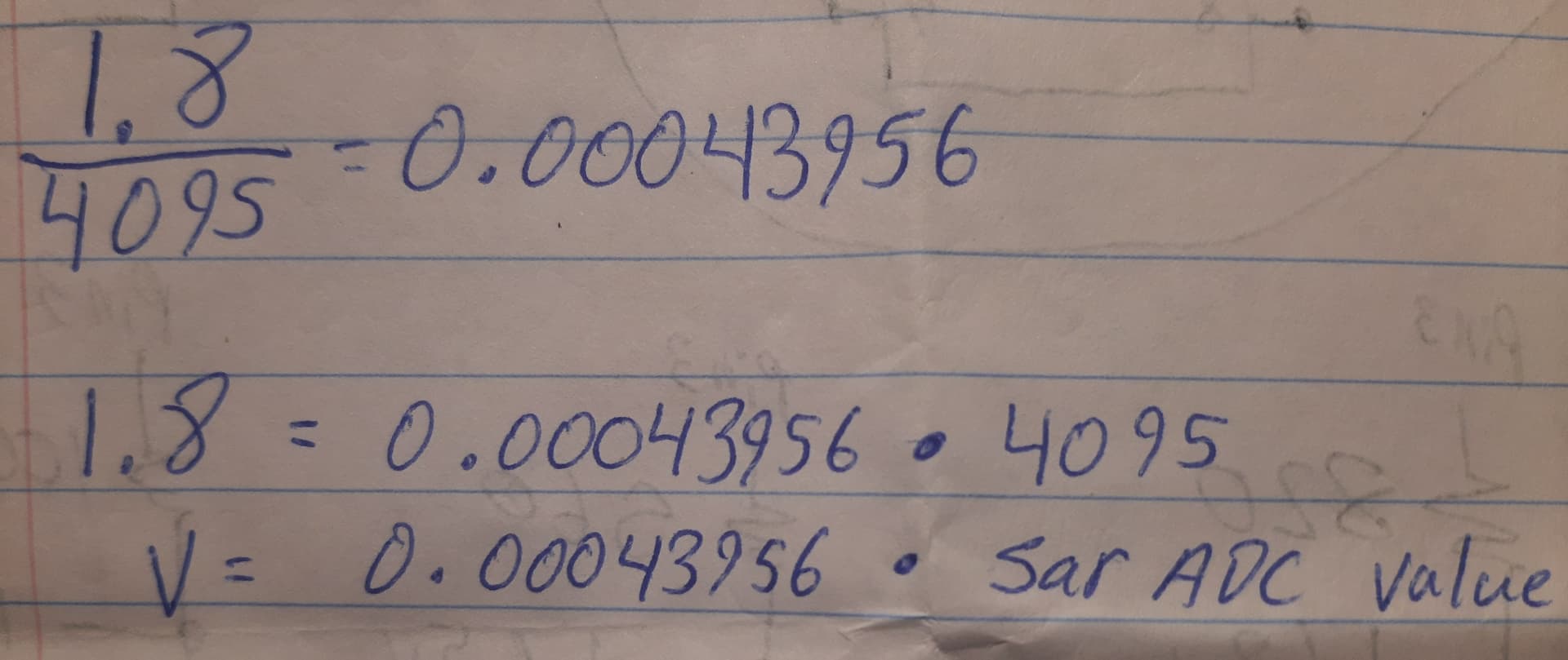
Also, based on documentation here concerning the AML-S905X-CC, it is able to safely measure voltages up to 1.8v, and it is critical to not exceed 1.8v.

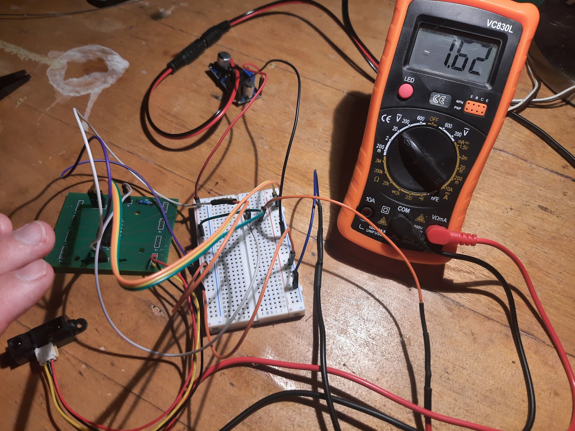
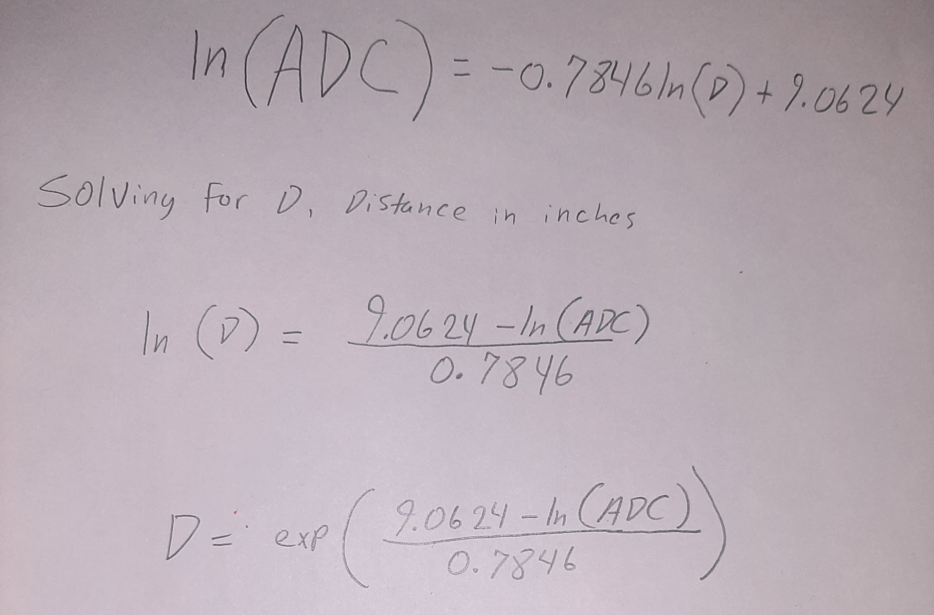
This means I’ll need a voltage divider circuit to bring the maximum voltage that my device outputs down to 1.8v exactly. This also means that I’ll need to map the new voltages that are output to distances via a customized mathematical formula. Which means I’ll need to build a testing setup to adjust distances and take several measurements, to produce an accurate formula.

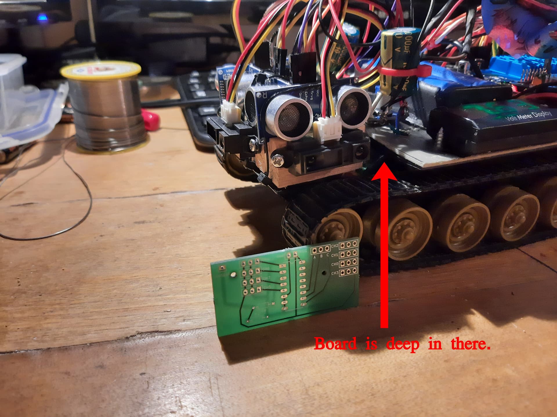
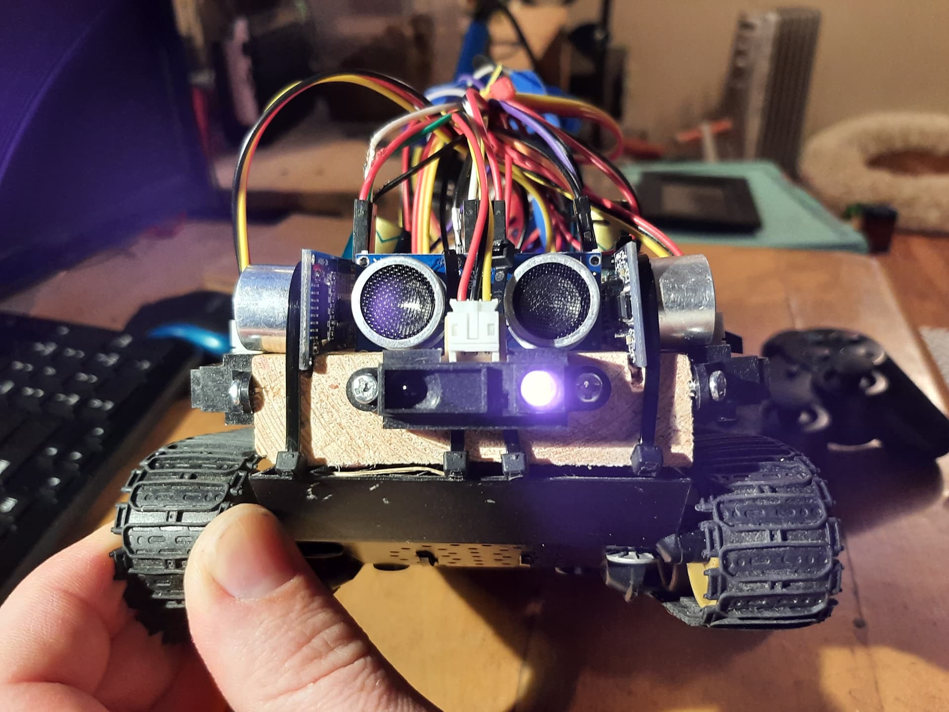
All this is in pursuit of improving my tank bot, to have multiple types of sensors that can be utilized.

Ok, first challenge I’ve realized is that there are two SAR ADC pins that can read voltages, and I want to use four sensors. This means I’ll need to share the two SAR ADC pins somehow. Initial thoughts:

  1. Create a way to turn off / on the IR distance sensors via GPIO outputs somehow. I’m thinking low current solid-state relays or something similar. Not sure how much the devices will like this frequent turning off/on or how long the device takes to initialize. This is probably not the best approach.

  2. Figure out how to switch between reading one value and another. The approach here would be the same as #1, figure out how to use a low current solid state relay or something similar to turn one output off and another on, and vice versa.

Solid state relay? I guess that would work, but it’s overkill. A plain old CMOS analog switch will multiplex the sensors (controlled by a few gpio outputs) and then you only need a single divider. CD4051 is the one I remember, gives you 8 inputs with, of course, a 3 bit select code. Or 4 inputs with 2 select bits and the other tied low. If the sensors really stay under 3.3V you shouldn’t even need any level shifters for the control lines…

You can just power and unpower parts of the circuit with a GPIO. It depends on the current draw of the sensor. GPIOs provide a few milliamps of current and if that is sufficient, you can use them to power and unpower the voltage divider and then use the SAR ADCs to determine the voltage.

You have to design the circuit so that the unpowered section does not affect the voltage on the powered section which would need some electrical engineering design that is beyond the scope of what we can assist with.

Your suggestion seemed very solid, I ordered several CD4051 and have them now. I went with this because of the switching frequency that the IC is capable of. If I read the data sheet correctly, at 5v input it can switch at something like 9 kHz on the low-end, which is plenty fast. @librecomputer I was worried with how acccurate the device would be if I powered it on/off rapidly. Also, I’m starting to run out of GPIOs :sweat_smile:

So I have given this GP2Y0A21YK0F IR Distance Sensor 5v input and have played around with it just now, reading the output on the yellow wire with a multimeter. The maximum voltage I’m seeing output is 3.1v. Though after passing it through a CD4051, I expect the voltage to be slightly lowered so this is the next thing to test. Then I can build a voltage divider and connect it all to the Le Potato, and start coding.