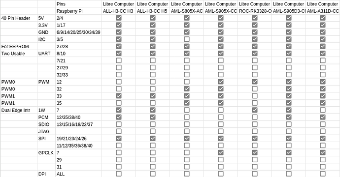
Within the SoCs are dedicated hardware controllers that can speak protocols such as but not limited to I2C, UART, or SPI as well as the ability to drive signals such as PWM, I2S, or SPDIF. These hardware controllers are connected to certain GPIO pins. The arrangement of these connections and the ability to use these hardware controllers to drive specific GPIOs is called pinmuxing or pin multiplexing.
Our CC boards feature 40 pin headers similar to those found on Raspberry Pi boards. To preserve compatibility and not have to re-engineer the peripherals, we try our best to maintain the same pinmux functionality on specific pins the best we can. Our boards have additional pinmux functionality not found on Raspberry Pi 40 pin header but they are not cover in this matrix and can be found on the GPIO maps available for our boards.
In upstream Linux and u-boot, these pinmuxes are defined on a SoC or SoC family basis in the disabled state as a device tree include (.dtsi file). The final board device tree (.dts file) enables specific pinmuxes used by the board as well as setup logical connection between various frameworks such as regulator, interrupt, and more based on the hardware layout.
In our technology stack, we make use of device tree overlays (.dtbo file) are applied on the board device tree. The overlay adjusts these pinmuxes on a running system via Libre Computer Wiring Tool to test and control hardware dynamically although with certain limitations.
